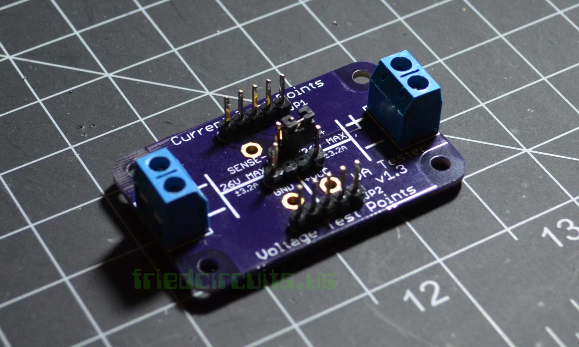
VA Tester Assembly
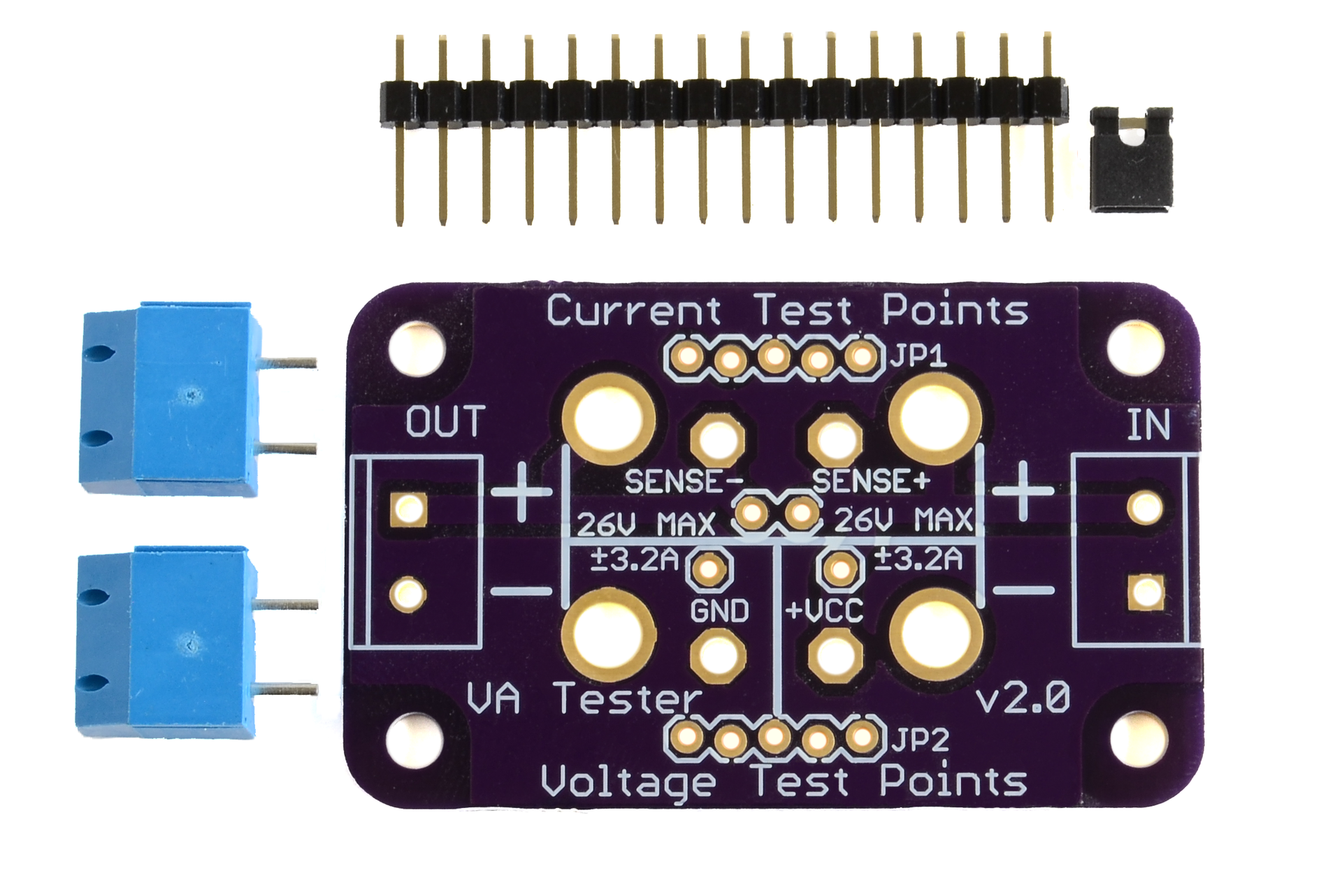
Parts
- 1x PCB
- 2x Screw Terminals
- 1x 14pin Male Header
Step 1
Depending on your configuration you don’t need to solder all the headers. So skip that parts you don’t want.
Start with breaking the 14p header into 3 sections.
- 2x 5 pin
- 1x 2 pin (Already separate)
- 1x 4pin
Take the 4pin header and remove the middle two pins with pliers or you can just push it on and it will push the middle two out. Then holding one side with your finger you can solder from back.
Step 2
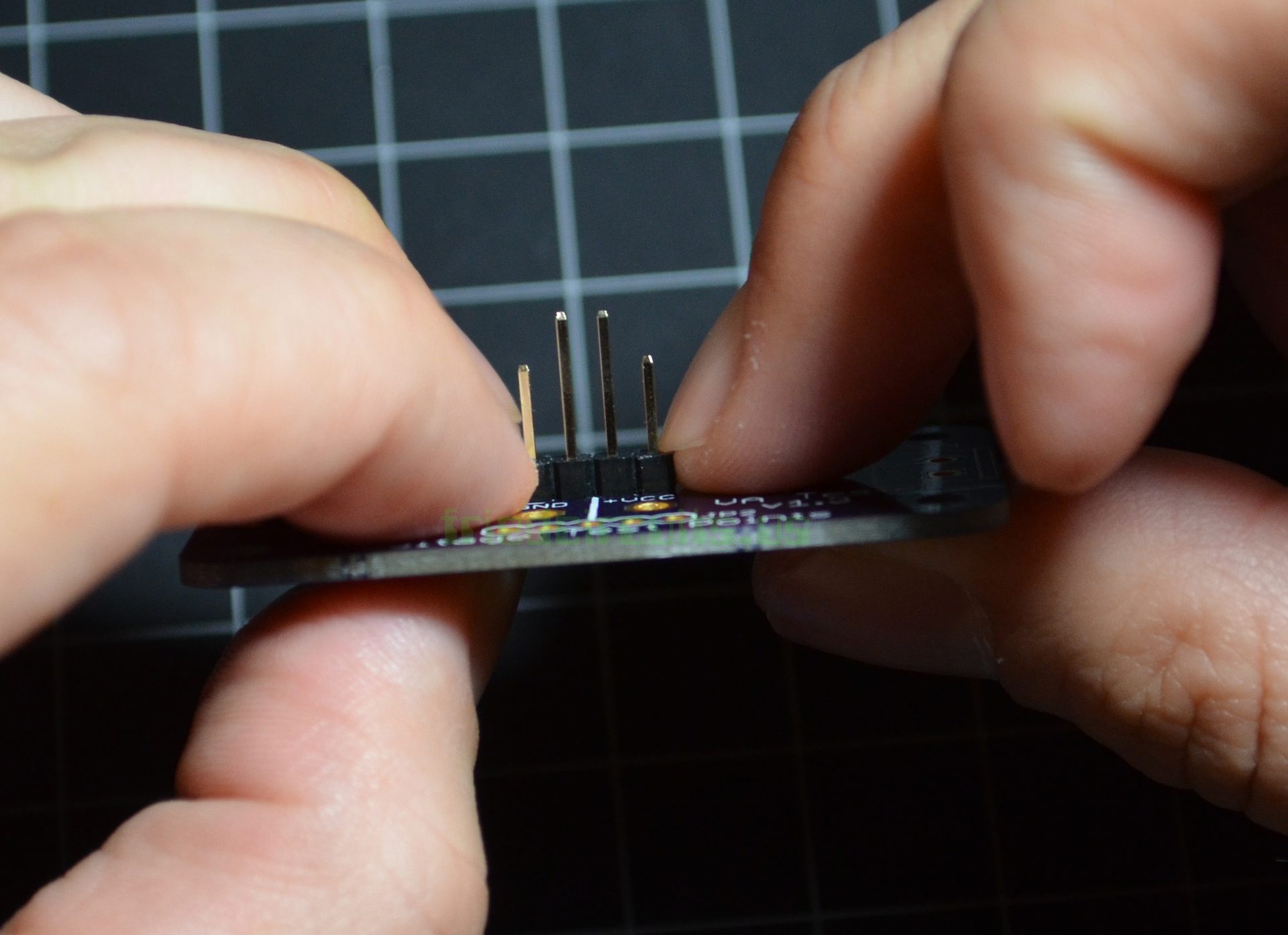
Place the 2pin header above the 4 pin header. If you are careful they may not fall out when you flip it over to solder. The design uses Sparkfun’s locking header footprint. But this works better with more than 2 pins.
Step 3
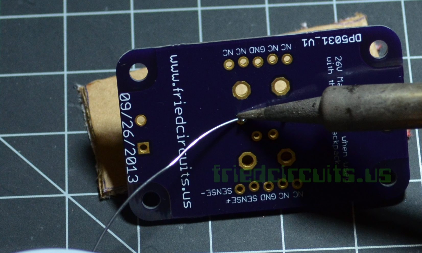
I found that it is easier to remove the pins before inserting them using pliers.
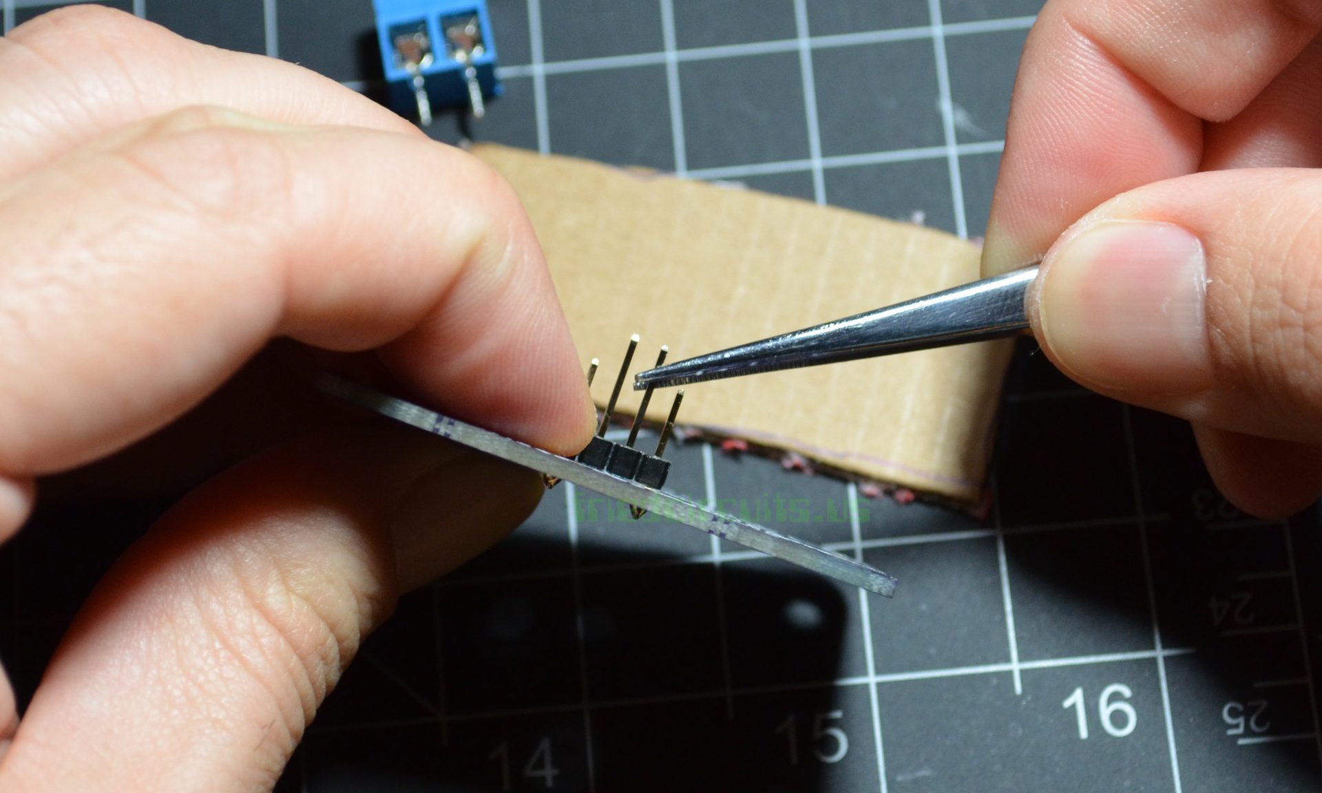
Step 4
Now you can solder the 2 5 pin headers which is used to connect to the OLED Backpack. I usually solder the middle of the 5 and then flip it over to check the alignment.
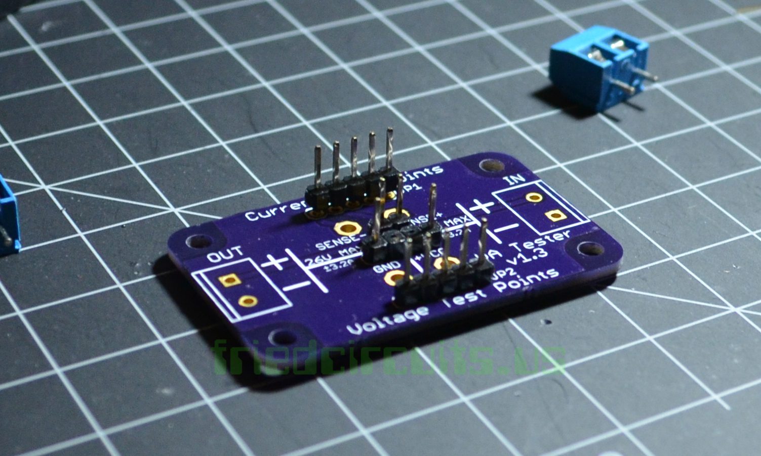
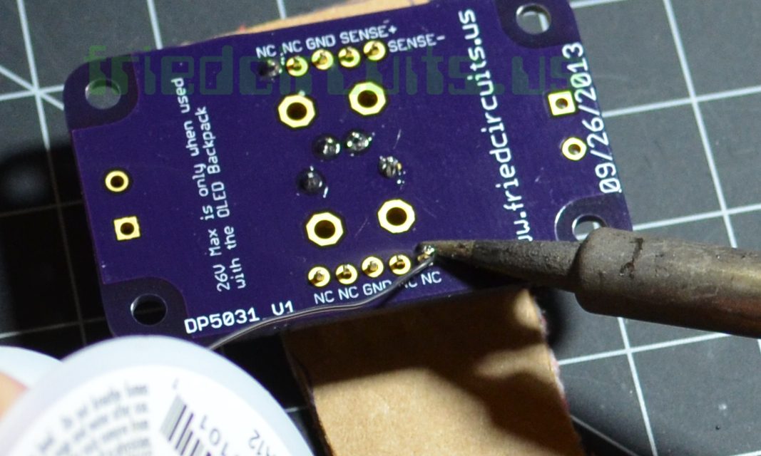
Step 5
Finally you can solder the screw terminals which are the easiest. If you have a variable temp solder iron you make need to turn up the heat when soldering the GND pins as the entire PCB acts like a heat sink.
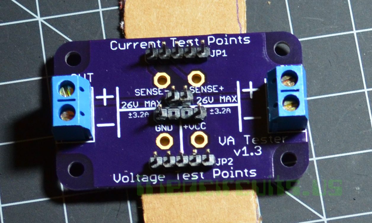
Step 6
When measuring current remove the jumper or hang it off to one side by only putting it on one header.