
Info: LED Matrix Link
Purchase: Tindie
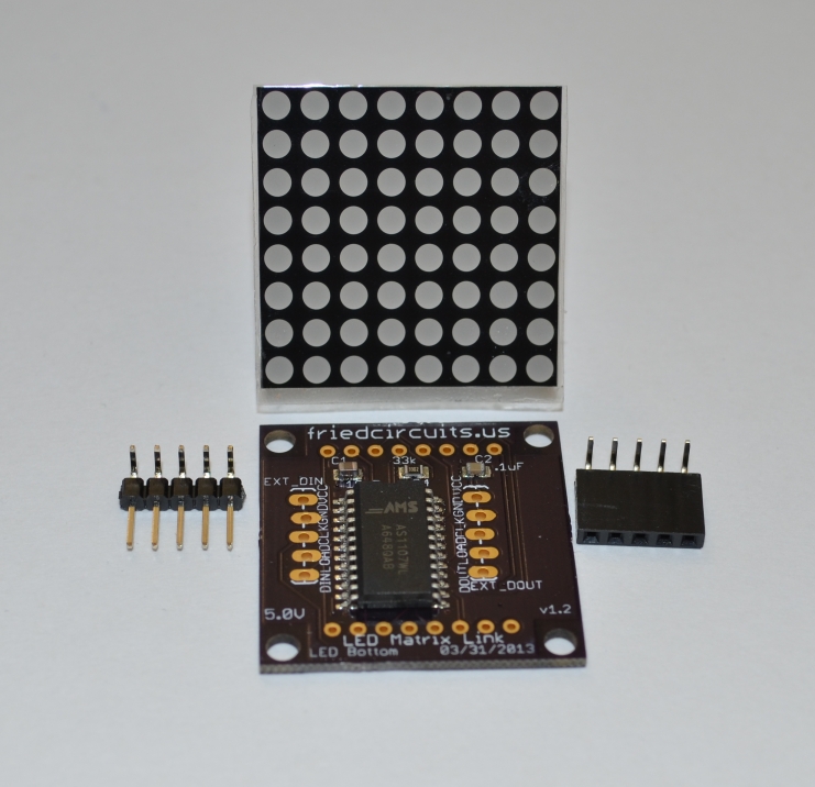
This kit comes with everything you need to make and control an LED Matrix from your own microcontroller. It comes with all the SMD parts pre-soldered. All you need to do is solder the header pins and the LED Matrix to the board. This kit can also be a great way to practice through-hole soldering.
Included:
1x PCB with soldered SMD parts
1x 3mm 8×8 LED Matrix
1x 5p Right Angle Female Header
1x 5p Right Angle Male Header

Included parts with LED Matrix Link
Solder Male and Female Headers
The headers are inserted on the same side as the IC and need to be soldered before you solder the LED Matrix.
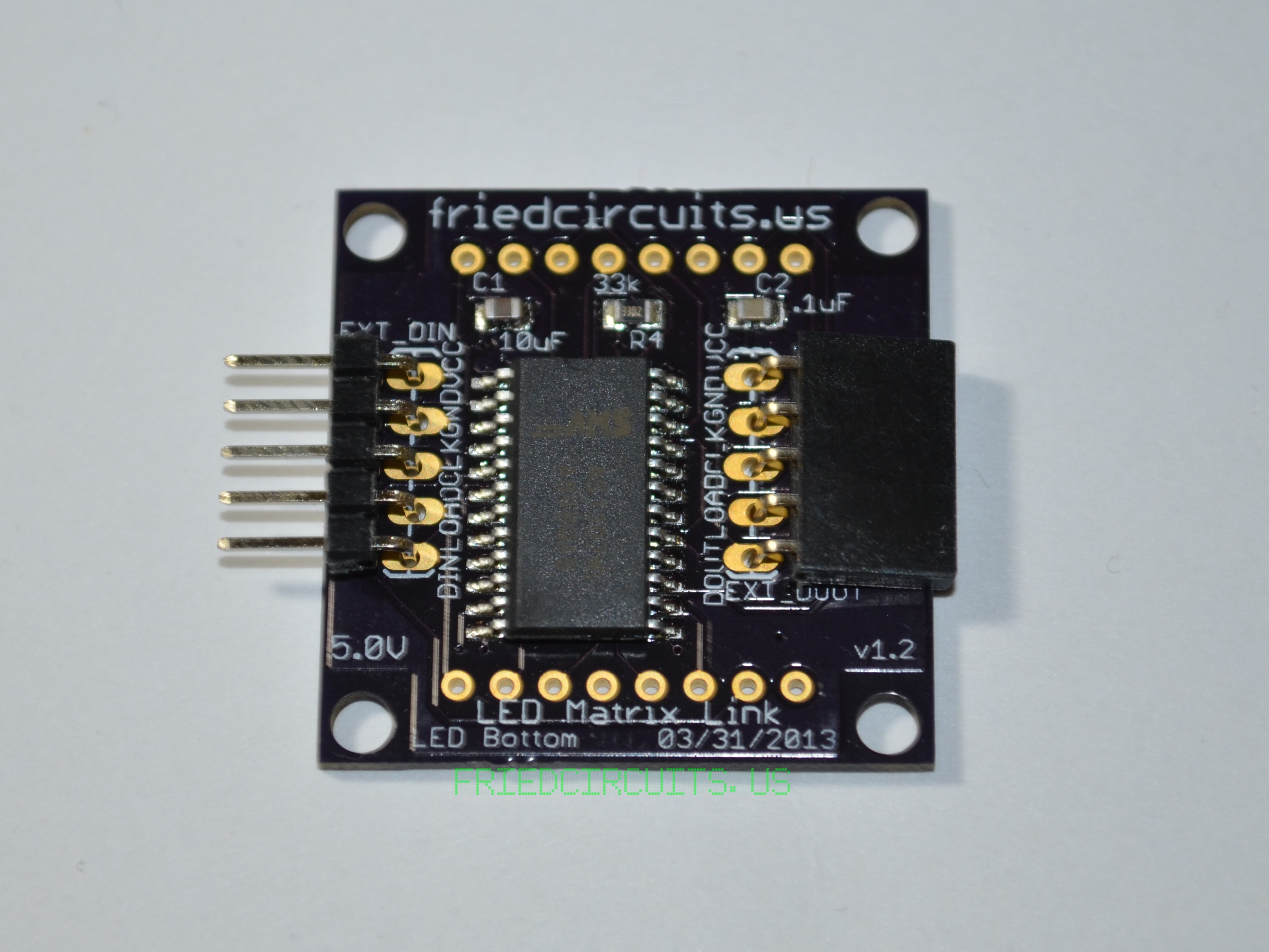
Headers ready for soldering
Starting with the female, insert it on the right and hold it straight. You may need to push it back a little. You want to make sure it is as straight as possible so that each LED Matrix Link fit together as close and evenly as possible. Solder one side, check alignment and then the other. Once you have good alignment solder the rest of the pins.
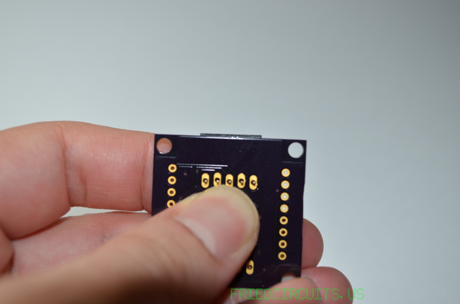
Align header so it is straight with PCB
Then do the same for the male header.
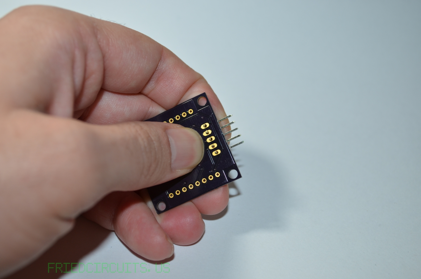
Hold male header in alignment for soldering
Solder LED Matrix
Before you solder the LED Matrix you might want to look at mounting options for your application. There might be ways of mounting it after it is soldered. I was thinking of some kind of plastic clip like the ones for motherboards. I was able to fit a M3 screw like the ones SFE sells. It only creates a small gap between the PCB and the LED Matrix. If use screws you may have to use every other hole since the edge of the screw sticks out.
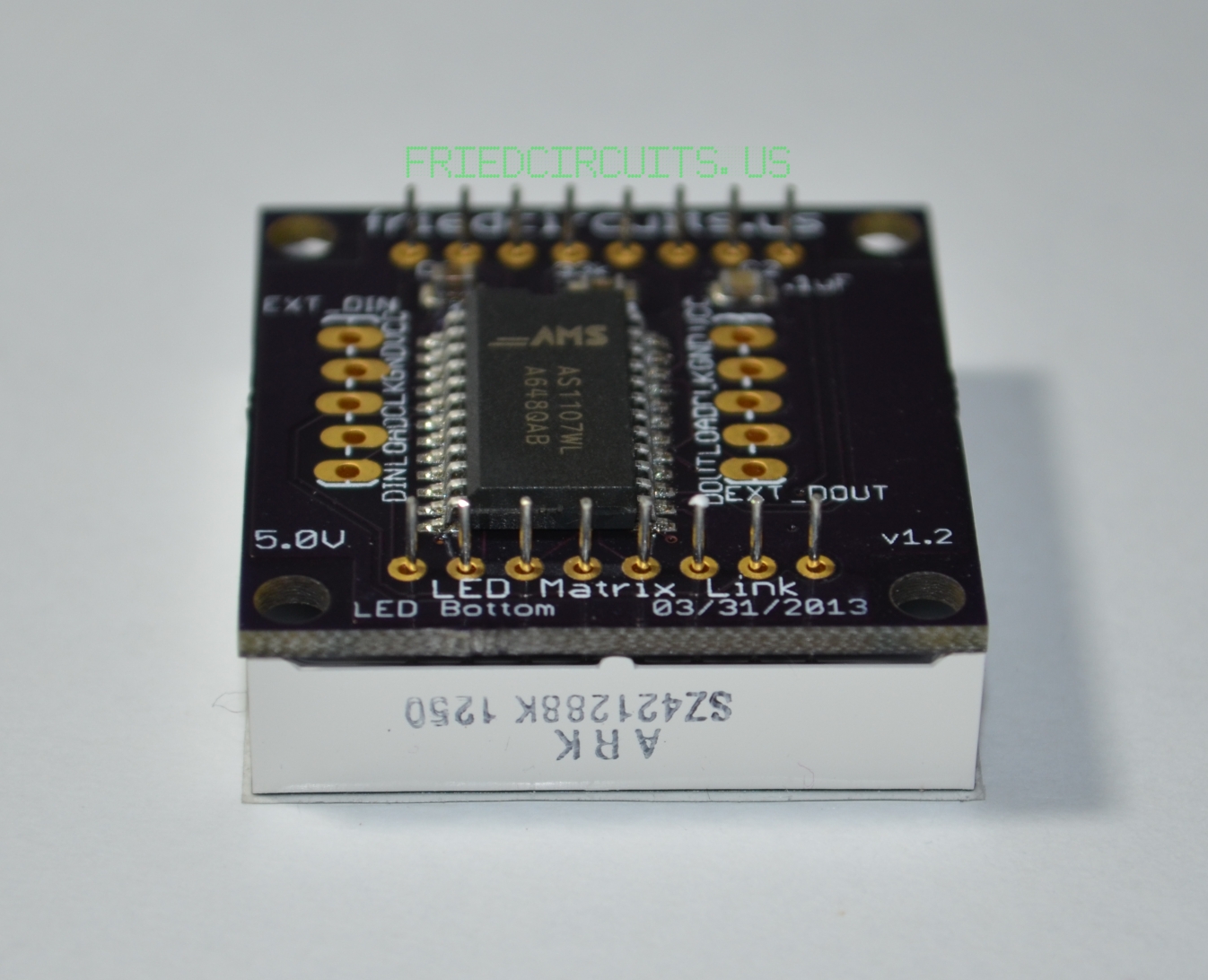
Align text on LED Matrix with bottom of PCB
If you look at the sides of the LED Matrix, one has text on it. That is the bottom side and should be aligned with the bottom of the LED Matrix PCB. The bottom is the side that is labeled LED Bottom on the silkscreen. Once aligned you can push the LED Matrix into the headers on the PCB. You may have to straighten a few of the pins to get it aligned with the holes. Solder on corner pin and check that is is flush with the PCB. Then do the same with the opposite corner. Once you are satisfied with the alignment solder the rest of the pins.
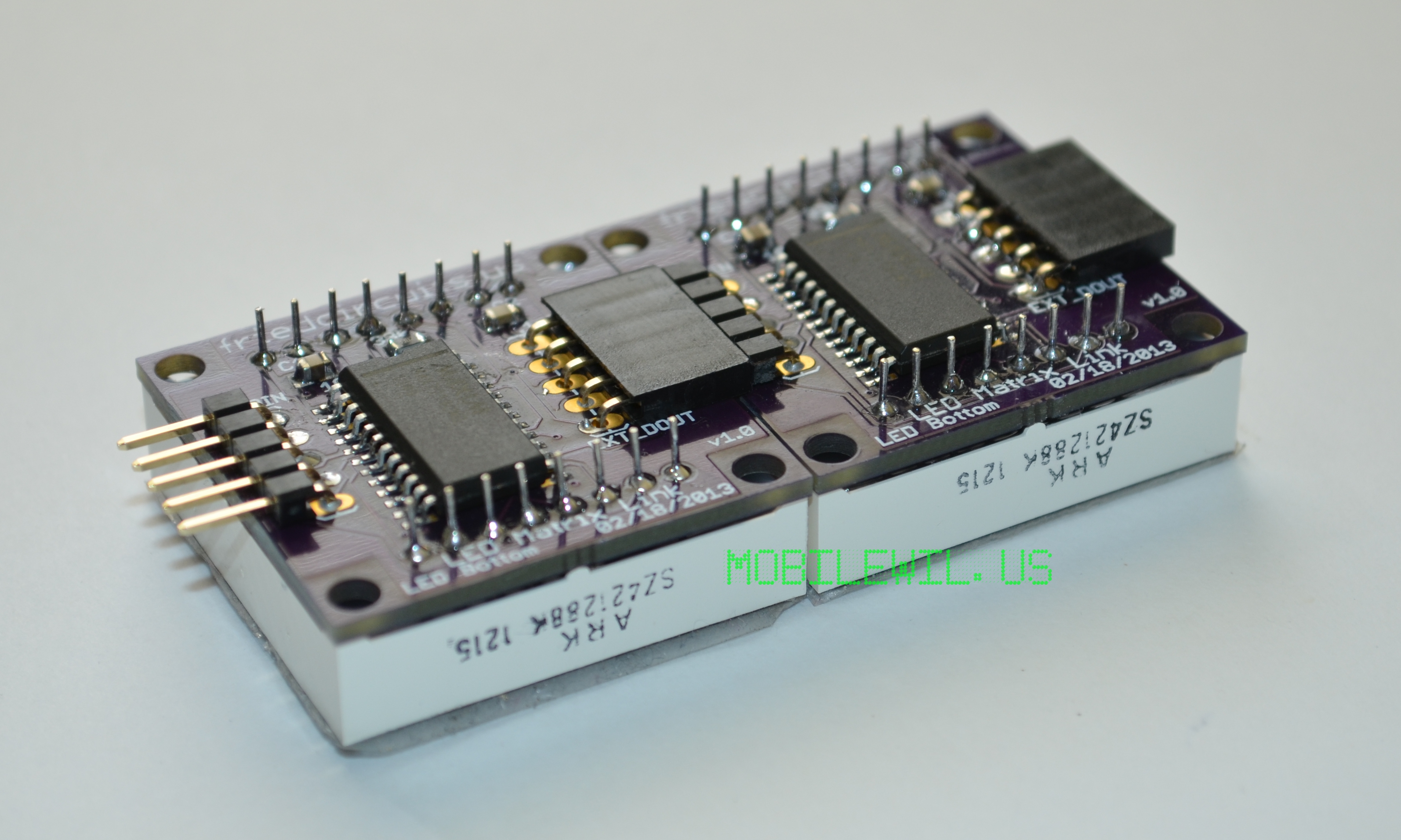
Assembled and linked