
Current Version: 1.1
Purchase: Tindie
Assemble: Here
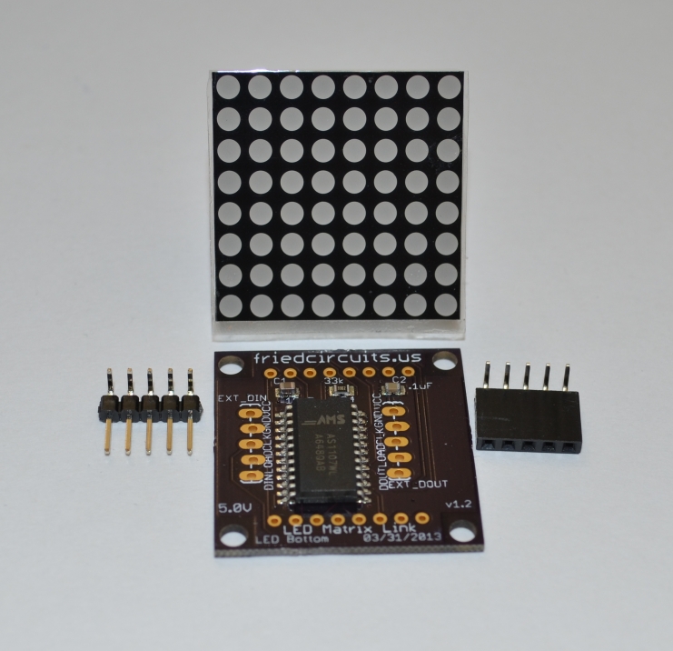
This kit comes with everything you need to make and control an LED Matrix from your own microcontroller. It comes with all the SMD parts pre-soldered. All you need to do is solder the header pins and the LED Matrix to the board. This kit can also be a great way to practice through-hole soldering.
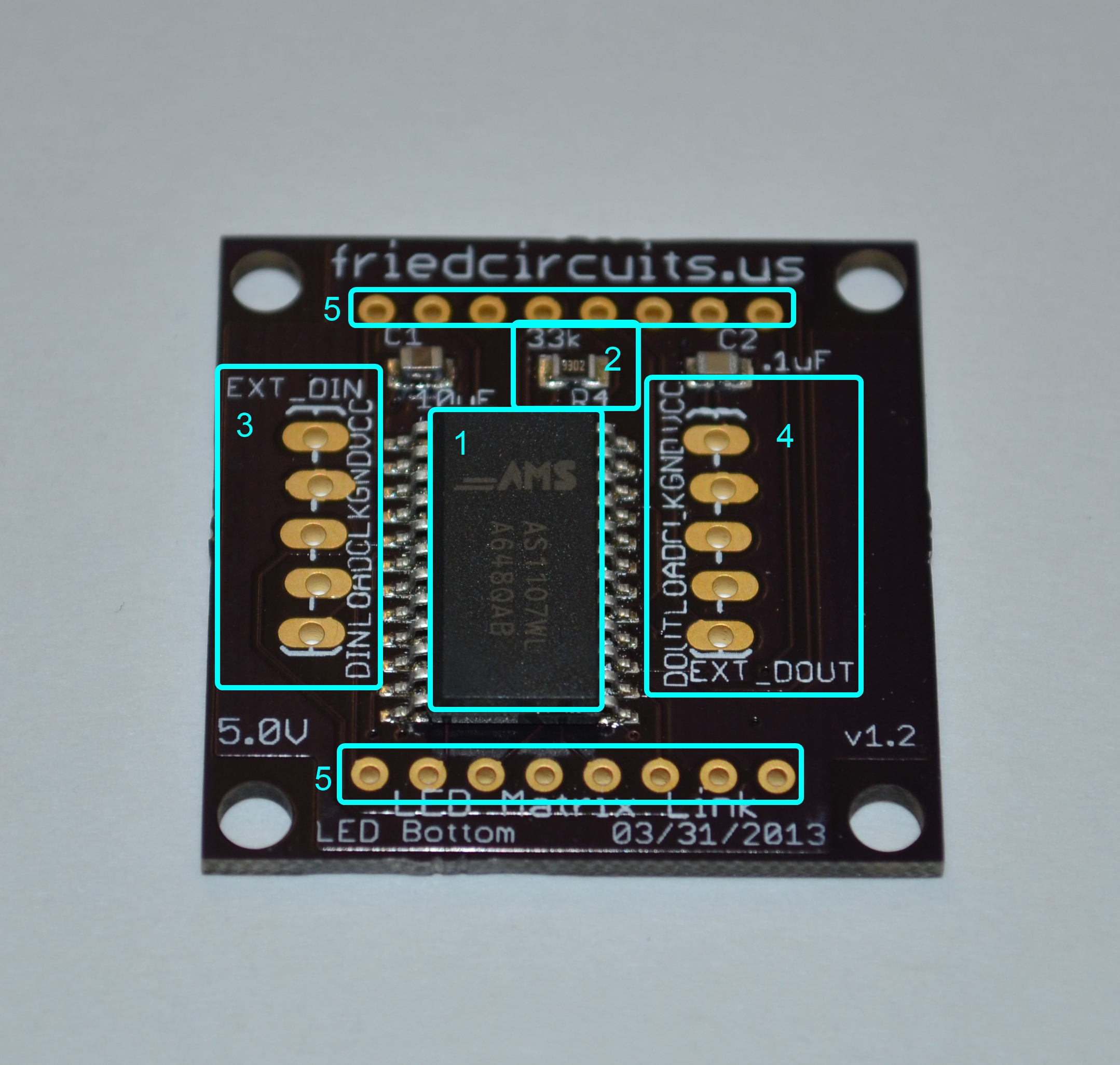
LED Matrix Link Labled
- AS1107 – 64 LED Driver from AMS
- 33k Resistor – Sets max current for the LED Matrix. See datasheet for AS1107
- Digital Input – Either from your own microcontroller or the LED Matrix Master
- Digital Out – Connection to another LED Matrix Link
- Header connection for 3mm 8×8 LED Matrix
You can find some sketch examples for use with a Arduino based micrcontroller on github: https://github.com/FriedCircuits?tab=repositories
We will add more over time.
Versions:
1-1.1: Development
1.2: First shipping version
Comments 11
Suggestion:
While I can figure this out on my own, it might be handy to have connection diagrams at least for Arduino if nothing else. The only point of confusion that may come about is “LOAD” is really a !SS (!CS) correct?
Rats, saved before I was done typing. Anyway… assembly suggestion — if you connect the male and female pins, then you can stick them in the appropriate holes on two boards, line those boards up and tack the headers in place. That makes it infinitely easier to get the alignment of the headers correct.
Also, I decided to raise up the displays so I could get access to the bolt holes. I used two 40×1 female vertical headers on each side as spacers. It was really tedious but I got it to work in the end. Hope this helps.
shimniok Good idea. Yes the load is the CS pin. Maybe this link will help in the mean time:
http://playground.arduino.cc//Main/MAX72XXHardware and
time. http://playground.arduino.cc/Main/LedControl
shimniok I will have to try that. Can you send a picture of how you setup the mounting?
MobileWill hope this helps clarify the LED mounting technique. LMK if you want a better explanation of how to mount the headers.
MobileWill no worries, I got it figured out pretty quick. But, might help others to see a hookup diagram.
I used 1/2″ #4 nylon bolts/nuts. Put a bolt through each hole, with a nut on the display side. This made leveling the matrix simple, just push the board gently so the bolts stand straight up. I left a bolt in diagonal corners, with extra on the ends. The master needed extra nuts since the LED is not there to hold them down.
The sample code I got from git had the initialization repeated in the loop, made the display flash something awful.
… the cable hanging off the desk made the first segment pop a wheelie it the photo. It really does sit flat.
Wow, looks great. The code does that because I use it when testing many links. That way I can swap them without powering off.
My todo list includes adding more examples. I was playing with game of life using multiple links. Few more things to figure out and then I can post it.
MobileWill Thanks.
I think the thing that seemed odd was when I plugged in the first segment and it was flashing, and when I plugged in the second unit, it was flashing differently. It though I had something wrong, until I swapped units and the intensity stayed with the location.
What is the purpose of the “digitalWrite(ledPin, HIGH);” in your example? I did not see it used in the LedControl library documentation.
I think this example would serve the purpose of allowing hot plug, show that all the LEDs are working, with a more even display:
#include <LedControl.h>
const short ledPin = 13;
const short brightness = 5;
void setup() {
Serial.begin(57600);
pinMode(ledPin, OUTPUT);
}
void loop() {
LedControl lc = LedControl(12, 11, 10, 8);
unsigned short devCount = lc.getDeviceCount();
for (int dev = 0; dev < devCount; dev++) {
/*The MAX72XX is in power-saving mode on startup*/
lc.shutdown(dev, false);
/* Set the brightness to a medium values */
lc.setIntensity(dev, brightness);
for (int row = 0; row < 8; row++) {
lc.setRow(dev, row, (row % 2) ? B10101010 : B01010101);
}
}
delay(500);
for (int dev = 0; dev < devCount; dev++) {
for (int row = 0; row < 8; row++) {
lc.setRow(dev, row, (row % 2) ? B01010101 : B10101010);
}
}
delay(500);
}
My wife requested I make a scrolling double-helix. I look forward to seeing your life implementation.