
Current Version: 2.0
Purchase: Tindie or FriedCircuits.us
Assembly: Here
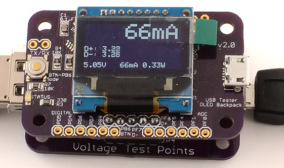
<Need Picture labled>
- Mode\Clear Button
- Status LED
- 128×64 OLED that shows graph, status readout, and peaks
- Connection to USB Tester
- Micro USB to host for data logging
- Unused Digital\Analog GPIOs. (PB6 is shared with the button and PF7\PF6 is connected to D-\D+)
Rear
- ISP programming pins
- Shared power solder jumper
Comments 9
Just got my USB Tester OLED Backpack 2.0, assembled it and now would like to know where to find the “Guide”, especially how to hook it up. BTW, is the S/W up to the latest levels (have v2.1)? Thanks. Helmut
hripke49 Hi, looks I never finish this page. Maybe this will help
http://learn.friedcircuits.us/usb-tester-and-phone-charging/
You do have the latest which is the first version to show firmware version.
How (or when) should i use a shared power jumper? When i connect backpack to VA tester and power it from lats say 20V supply it will not destroy a backpack board? Or mayby there is some regulator on board to power atmel chip from various voltages?
holovitz Hi, In the case of the VA Tester the shared power doesn’t matter. With the VA Tester the backpack needs its own power source. The shared power is for the USB Tester if you want to use seperate power. One use is if you want to test a battery till it is completely dead.
Hi, got a question about using the OLED backpack with the USB Tester. I was surprised to see that I could charge a battery power bank, by plugging a micro-USB into the backpack board, and leaving the USB tester micro-USB port unconnected. Are the power lines on that side simply tied together?
I suppose I should be disconnecting the Shared Power jumper – how do I do this?
Thanks!
hotsoup Hi, yes they are but you can cut the shared power jumper. Just use the a thin blade to cut the trace between the two solder pads. If you need to reconnect it you can solder the two pads back together.
MobileWill hotsoup Thanks for the quick response! I cut the trace with a scalpel blade, checked that it was an open circuit, and now it works the way I need it to. Thanks!
I was also surprised to find that the shared power jumper defaulted to connected.
I assumed that it was necessary to solder across it to connect, but there is an INVISIBLE connection under the solder mask that means it is connected until you cut it with a scalpel.
I think this should be noted in the documentation as part of the assembly process. CUT the invisible trace if you don’t want to share power.
Thanks for the feedback. The pinout/info cards are coming along. I will add the note to the assembly.