
Info:
Purchase: Tindie or FriedCircuits.us
- 1x Backpack PCB SMD Parts assembled
- 1x 128×64 OLED
- 2x 5pin Female Header
Note: By default the solder jumper on the bottom is connected to allow shared power. This means that the device you are measuring will also power the backpack (Except for the VA Tester). It will not affect the measurements. If you want to have separate power you can use a blade to cut the trace between the two pads. This can be useful if you are measuring a battery for example.
| 1. The easiest way to solder the headers is to place the USB Tester | 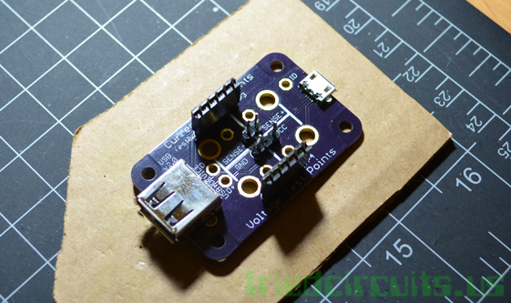 |
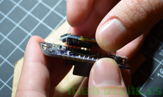
| 2. Place the backpack on top and solder the middle header. Then you check underneath that the female headers are flush. | 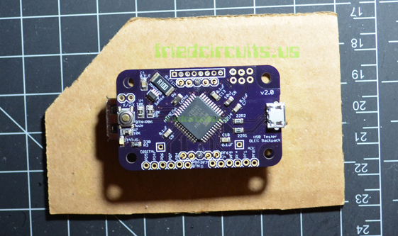 |
| 3. Solder the rest of the headers. | 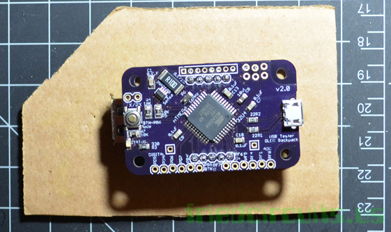 |
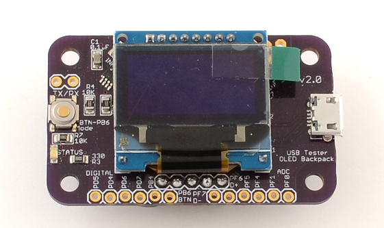
| 4. Remove the backpack and place the OLED display and flip it over. |  |
| 5. Solder the two ground pins which are the ones by themselves. It may take longer to heat up since they are connected to the ground plane. Check that the display is flush with the PCB. | 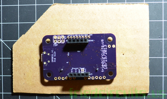 |
| 6. Solder the rest of the pins. |  |
| 7. Complete! |  |