Current Version: 1.1
Purchase: Tindie
Assemble: Here
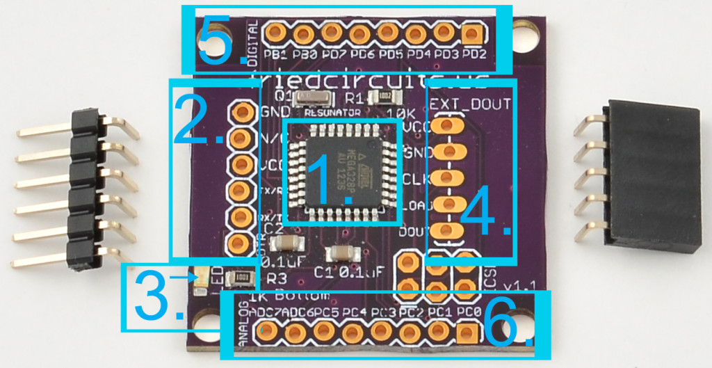
- Atmega328p @ 16MHz- Arduino compatible with bootloader and demo sketch
- FTDI – For use with FTDI cable or SFE Basic for uploading new sketches or serial output to USB
- Blue LED – for your own use (PIN 13)
- Digital Out – Connection to LED Matrix Links
- Unused Digital GPIOs
- Unused Analog GPIOs
Versions:
1.0: Development
1.1: First shipping version
How to use: (Pictures coming)
The LED Matrix Master comes with the Arduino Uno Bootloader preloaded and a simple sketch to test any attached LED Matrix Links.
There are two ways you can upload code:
- FTDI Cable
- AVR Programmer (Will overwrite bootloader)
After assembly the left side attaches to your FTDI cable and the right so your LED Matrix Links.
If you want to try uploading test code you can download the test sketch from github: https://github.com/FriedCircuits/FC-LED-Matrix-Master/tree/master/Code
Copy to your Arduino projects folder for example
c:\users\username\my documents\arduino\projects\LED_Matrix_Link_Test_Display\LED_Matrix_Link_Test_Display.ino
You will also need the LEDControl Library which you can get below and has a lot of information about using the library and how it works.
http://playground.arduino.cc/Main/LedControl
Open the Arduino IDE, open the sketch by either File/Open or it should show up under File/Sketchbook.
Double check the FTDI cable is connected, the BLK wire on the FTDI cable is usually GND and connects to the left side top pin.
Select the COM port of the FTDI cable and board type Arduino Uno.
Now you can click upload and it will compile and upload to the LED Matrix Master.


