USB Tester 2.0 Assembly
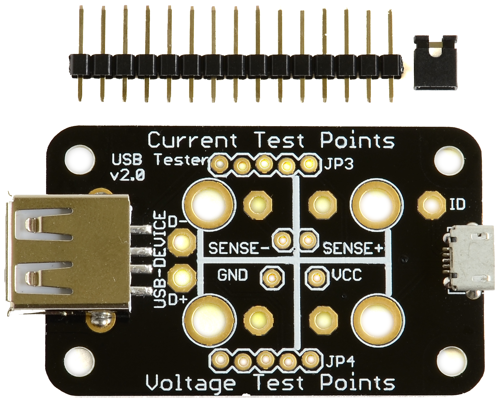
Included Parts:
- 1x PCB
- 16pin Male Header
- 1 2pin Jumper
The assembly is similar to the VA Tester, except only one pin to remove. Having the voltage pins being separated allows easy use of test clips and stops accidental placement of the jumper.
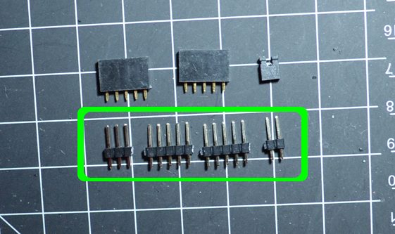
Cut apart the header pins
In the following arrangement:
- 1x 2pin
- 2x 5pin
- 1x 3pin
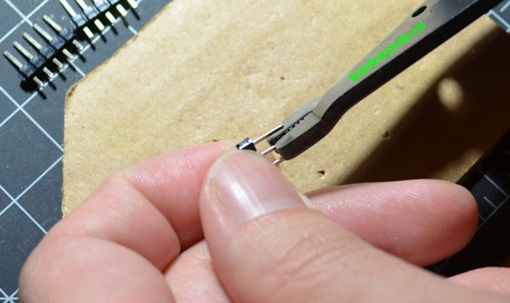
Remove the center pin
Using pliers remove the center pin for the 3pin set.
Insert the headers
Insert each header in and flip over. You may want to put cardboard underneath as the pins get hot and can melt anything you are resting the USB Tester on.
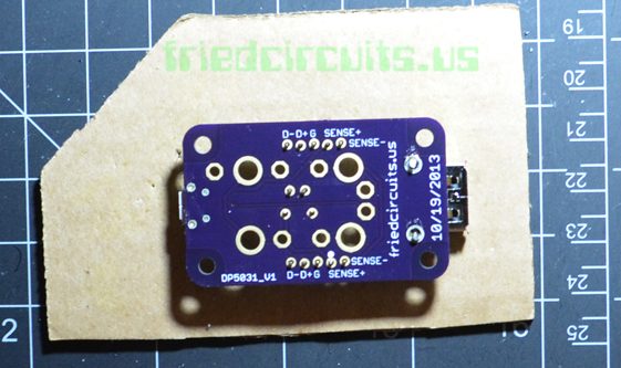
Tack one pin from each header
Solder 1 pin from each header. Flip over check each header that it is flush and straight to your liking.
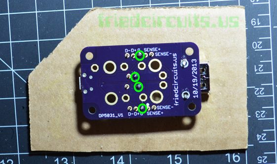
Solder the rest
Flip back over and solder the rest of the headers.
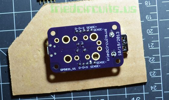
Done
Now you are set. When not measuring current use the jumper on the 2pin header.
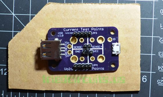
Check out the backpack assembly here: /usb-tester-oled-backpack-2-0-assembly/