USB Tester Assembly
Included with USB Tester:
- 1x PCB
- 1x 14 pin header
- 1x Jumper
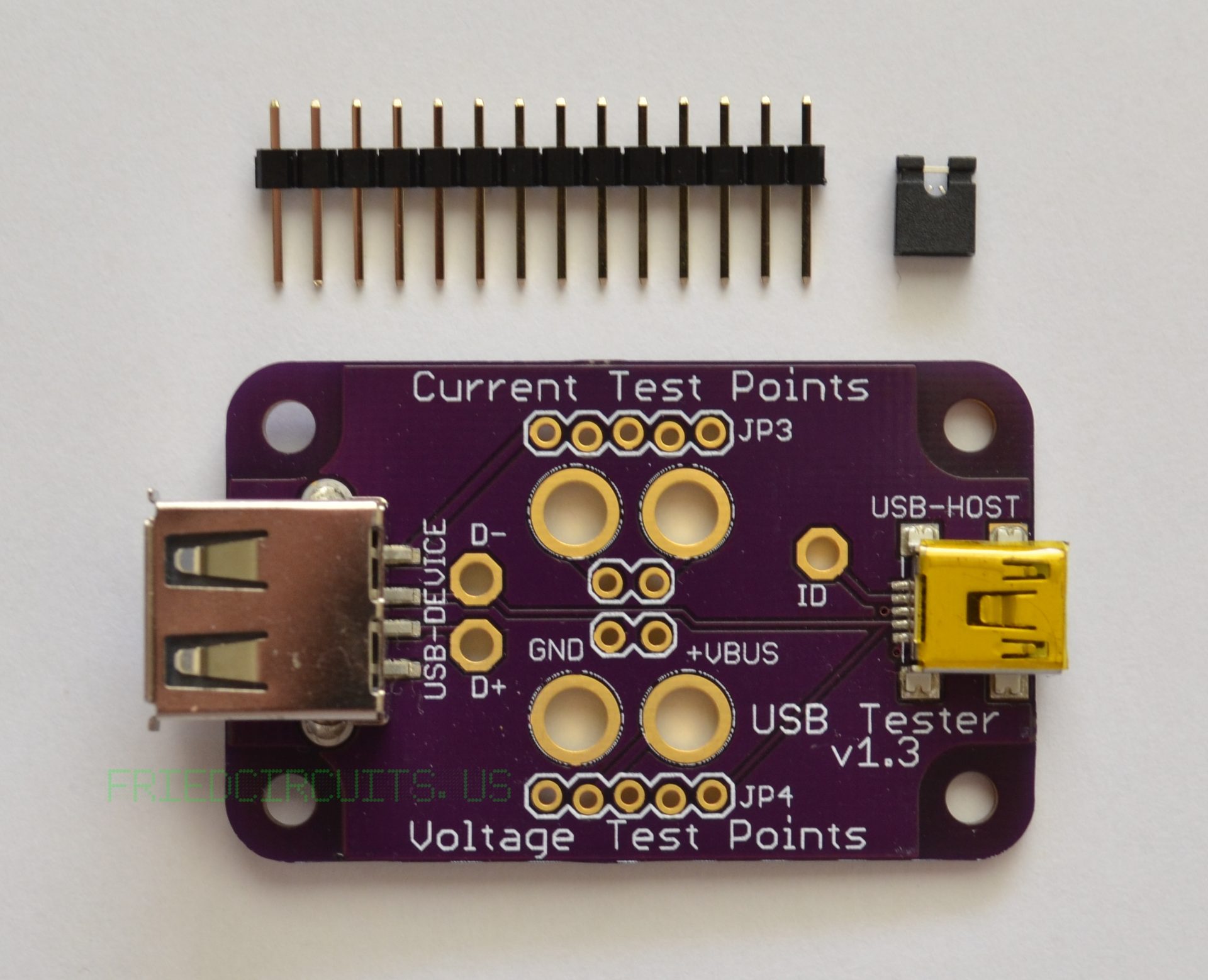
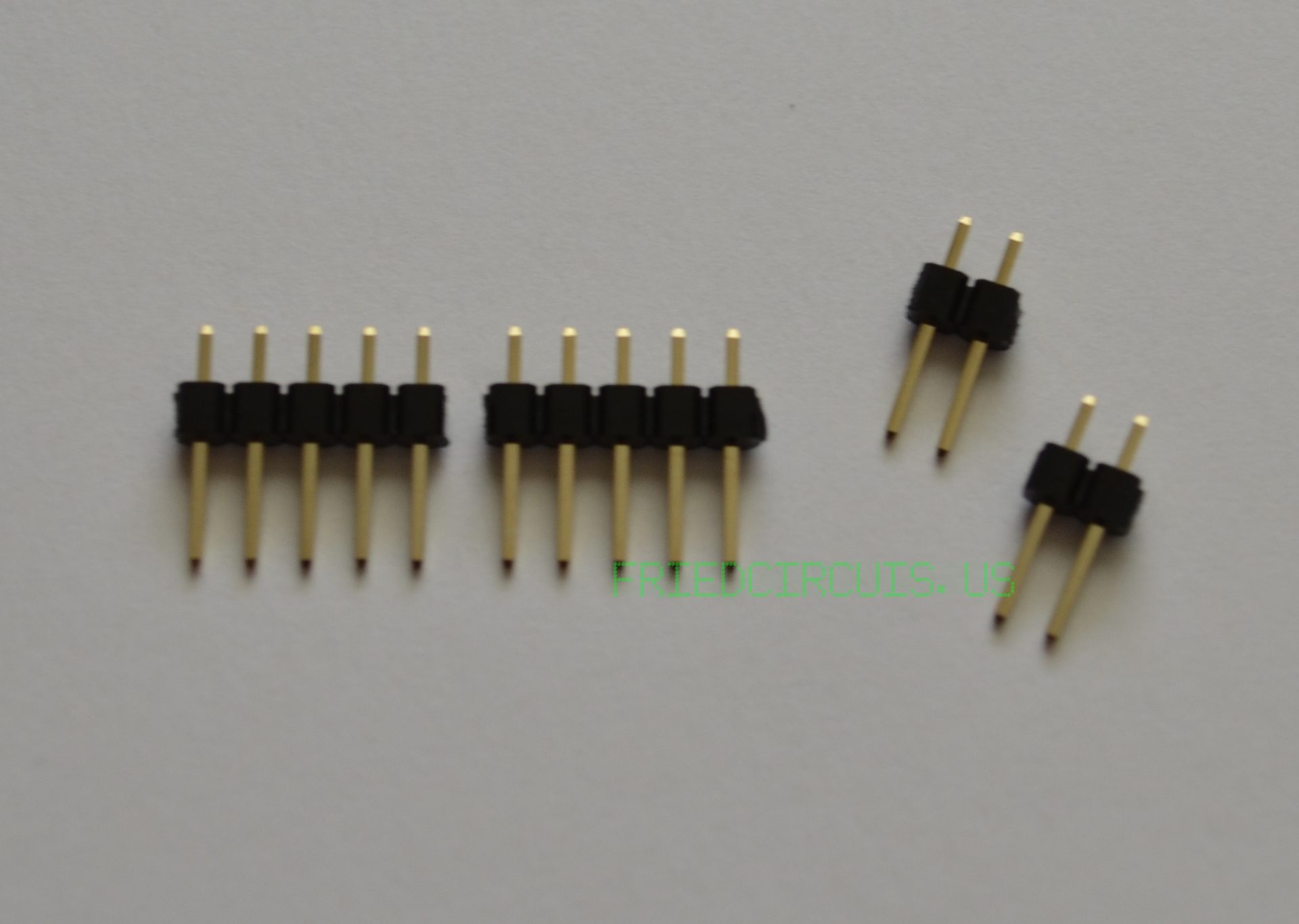
Separate the 14 pin header into two 5 pin and two 2 pin as seen below
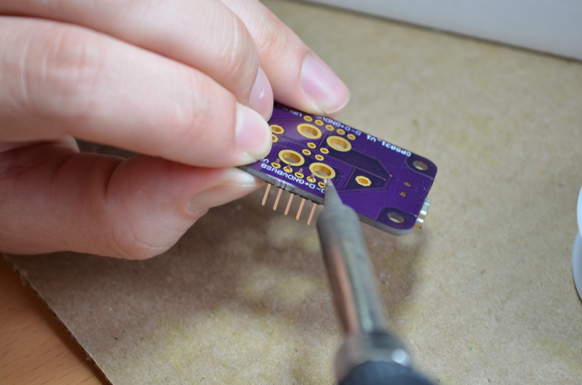
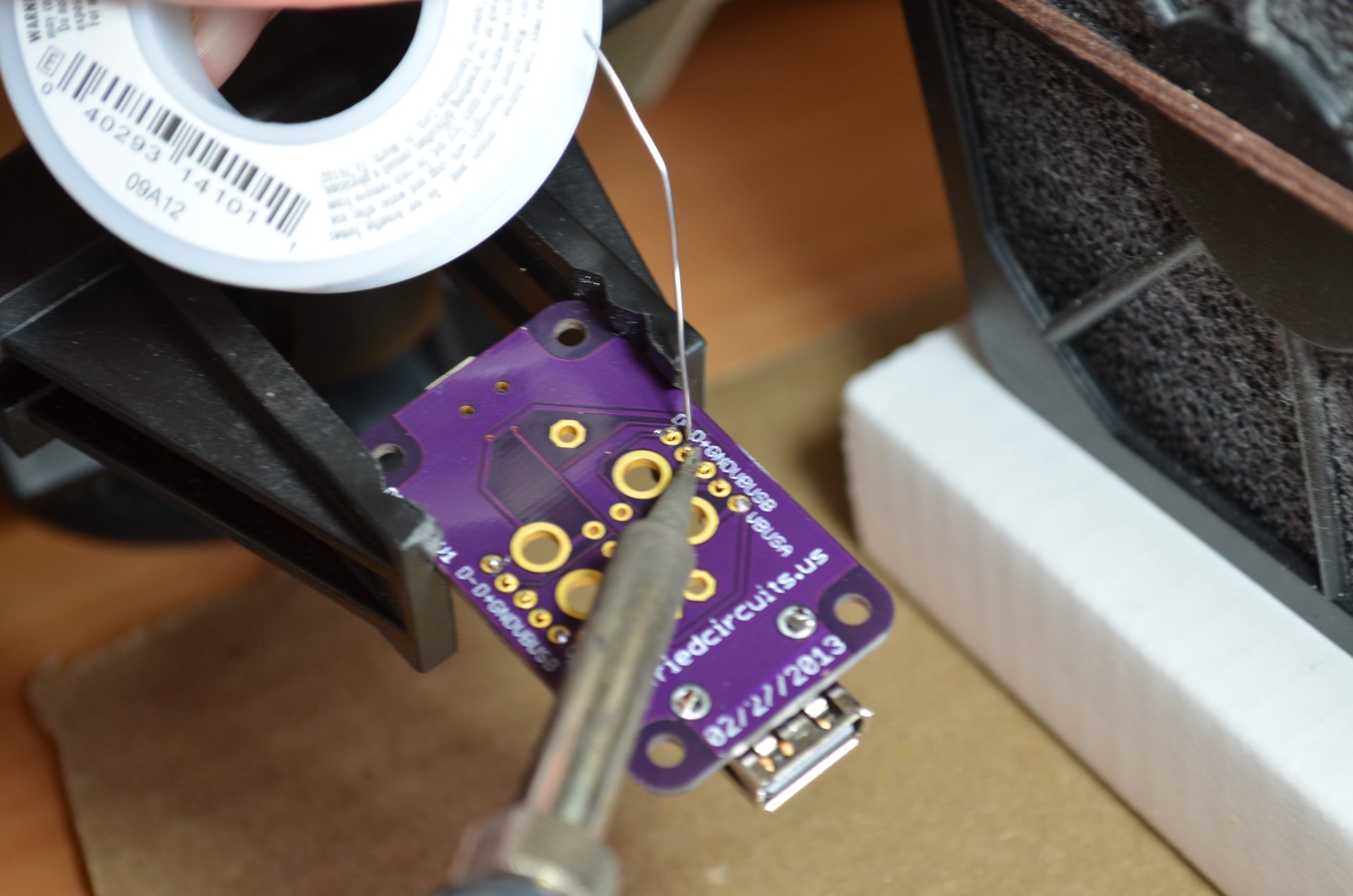
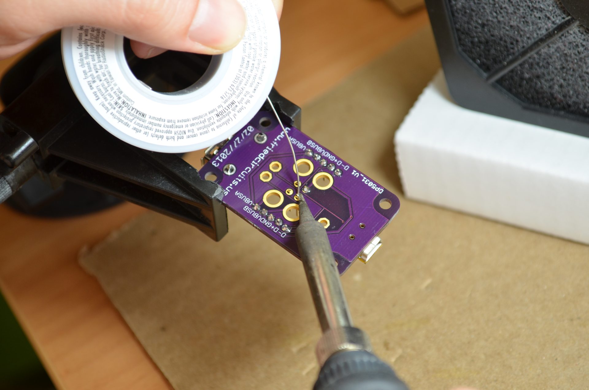
Solder the 5 pin headers on to the USB Tester
I use my nail to hold it and then solder one side. Be careful not to burn your finger! Then you can make sure it is straight. Solder the other side and check again. Once you are satisfied, solder the rest. Repeat for the second 5 pin header.
(Optional) Solder the 2 pin headers
Since the PCB uses Sparkfun’s locking header footprint, the 2 pin will stay in while upside down. You can insert both and solder.
The USB Tester is now ready for use
If you want to measure only voltage attach the jumper to the top set 2 pin headers. Remove for testing current.
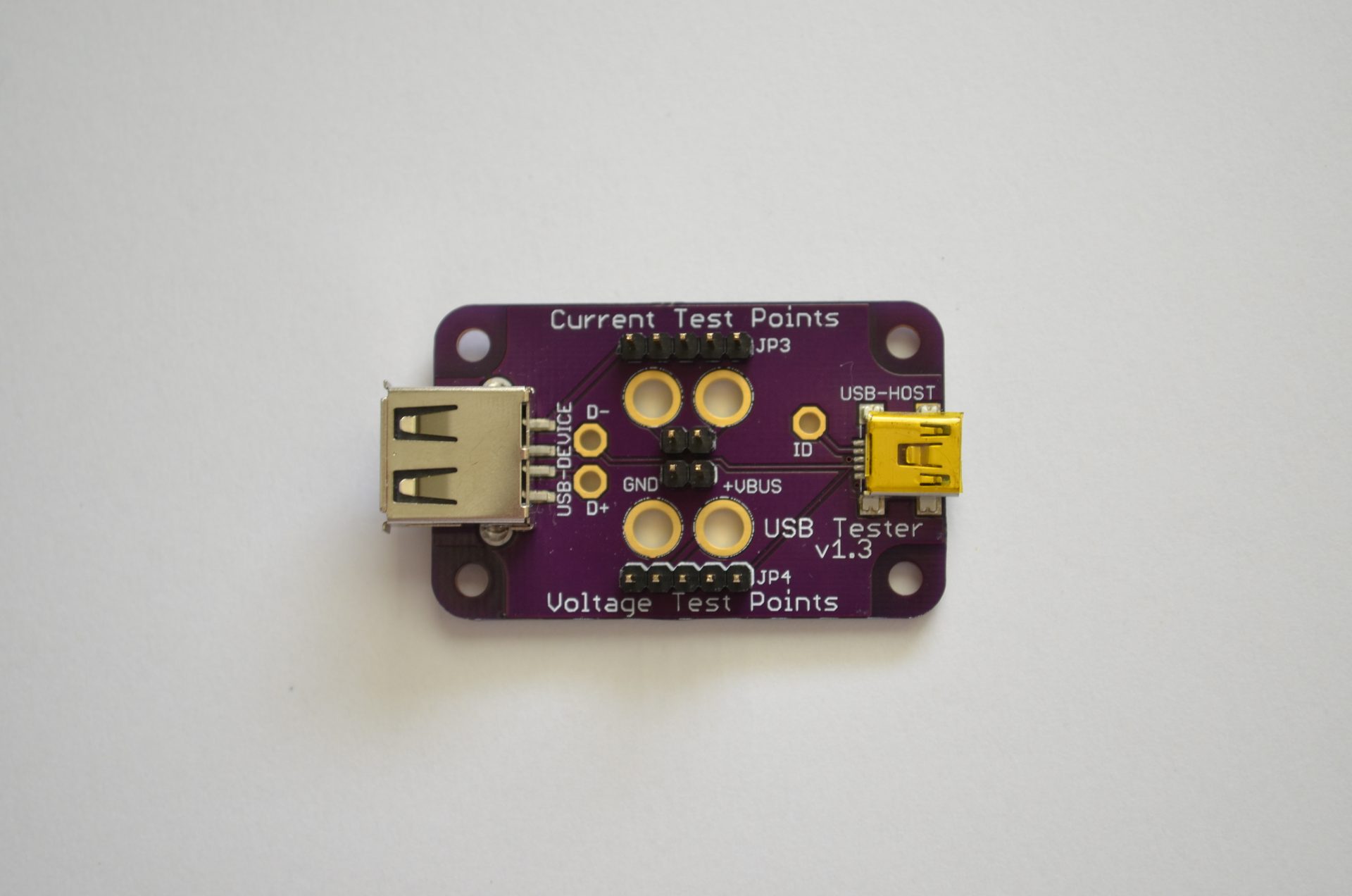
Never put the jumper on the lower 2 pin header as this will cause a short from VCC to GND.
For more information on how to use the USB Tester you can find the guide here.