
Current Version: 1.1
Purchase: Tindie and Friedcircuits
Assembly: Here
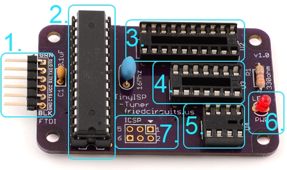
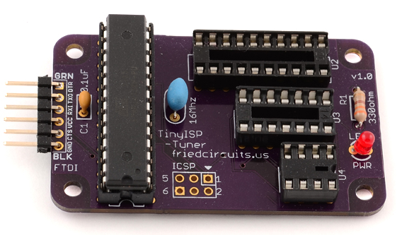
TinyISP-Tuner Diagram
- FTDI Connection
- ATmega328p – Runs TinyISP Sketch configured with Tuning enabled. (Pre-programmed)
- 20pin Socket for ATtiny2313\4313
- 14pin Socket for ATtiny84\44\24
- 8pin Socket for ATtiny85\45\25
- Status LED controlled by ATmega328p and TinyISP Sketch on pin 9
- ATmega328p ICSP Program header
Versions:
1.0 Development
1.1 Initial Shipping – Adds 0.1uF Cap and 10K Resistor to reset line
Guide:
The TinyISP-Tuner makes programming and tuning ATtiny Microcontrollers a snap. Before you begin there are few things you need to download
- Arduino IDE
- TinyCore Follow the directions in the readme file
- TinyISP (Only needed if you want to re-program or change options on the ATmega328p)
- TinyTuner2
A few notes about using the TinyISP-Tuner
- Never have more than 1 ATtiny in one of the sockets.
- Always check the orientation before powering up.
- Always power down before inserting\removing an IC.
- If you don’t want the hassle of removing the IC you can slightly push it in the socket instead of all the way.
- You can use this just to program ATtinys without tuning them or if you have already tuned them.
Setup: (At this point, TinyCore should be installed)
Once you extract and run the Arduino IDE it creates a project folder. In that folder extract the TinyISP(if needed, see configuring TinyISP below) and TinyTuner2.
<Picture of connections>
Open the Arduino IDE and open File|Examples|TinyTuner2|WriteToEEPROM
Only thing you need to modify that helps is after
void setup(void)
{
add
delay(4000);
This gives you some time to open the serial monitor and enable debug monitoring so you can see the output.
You can also use the other example if you don’t want to save tuner value to EEPROM. Its called PrintUsingKnockBang
Hardware Setup:
Attach the ATtiny you want to program\tune into one of the sockets with the notch facing the LED. To make it easier to remove you don’t have to push the ATtiny all the way down.
Plug the FTDI cable with the Black\GND at the bottom of the header.
Programming:
Under Tools|Programmer make sure it is set to Arduino as ISP.
Set Board to Attiny your are using and the speed, I would use 8Mhz.
Select Tools|Burn Bootloader
Once it is done
Select Upload|Upload using programmer
Open the serial monitor and make sure speed is 19200 and send a “!”. Now you should see the output of the tuning status. If you used the write to EEPROM version it will say when it has saved. If you used the PrintUsingKnockBang version it will print the value you need for tuning and how to add to your code.
How to read from EEPROM
Once you have saved the tuned value to EEPROM you need to load it for each sketch you use. Using EEPROM is helpful so you don’t have to change your code for each different ATtiny you use.
At the top add:
#include <EEPROM.h>
Then in your setup function add:
If using :
8Mhz
OSCCAL = EEPROM.read(E2END);
1Mhz
OSCCAL = EEPROM.read(E2END-1);
16Mhz(Not sure which ones support internal 16Mhz)
OSCCAL = EEPROM.read(E2END-2);
Configuring TinyISP
Here is the settings that are used in TinyISP. This is useful if you want to reprogram the ATmega328p with TinyISP.
Once the TinyISP sketch is opened
Switch to the tab called _TinyISP_BuildOptions.h and make sure the following is set.
- #define PROGRAMMER_SPI_CLOCK NORMAL
- #define RELAY_KNOCK_BANG_ENABLED 1
- #define TUNING_SIGNAL_ENABLED 1
Example code and design files available on Github: https://github.com/FriedCircuits/FC-TinyISP-Tuner
Comments 14
Hello, I recently ordered and have been using this programmer. I am very happy with it, it is very well designed. I followed your instructions to calibrate the tiny chips and I see there is a sort of serial monitor functionality used to get data back and forth from the tiny chips to the computer. Could this allow me to do serial debugging through the programmer from the tiny chips? If so, do you have a sample sketch a and configuration for how this could be done?
Thanks,
-Marco
mellamanjefe Hi, yes there is. If you send a ! to the serial port it will toggle monitor mode. Here is a link with a good example. http://www.ernstc.dk/arduino/tinycom.html Use the TinyKnockBang example which is how the serial monitors works to get serial output via the programmer.
Let me know if that works. You can also email support@friedcircuits.us
-William
MobileWill
Thanks! I will test it out.
William,
It worked like a charm. The only issue I had was that in line 52 of TinyKnockBangDebug.h I had to comment out the definition for fstr_t as per a post in the arduino.cc forums in order for the compiler to build the library. I mention this in case someone else runs into a similar issue.
Thanks,
-Marco
mellamanjefe Hmm, interesting. Thanks for posting that. Which version of the Arduino IDE are you using?
Sorry for the late reply. I am using 1.0.5-r2.
Is there a way to use this with a barebones Arduino kit that has the full blown Atmel AVR 168/328p. There is no provision for a x’tall or resonator, and I need accurate timing… Thanks!
rasyoung Hmm, so you want to use the internal oscillator in the Atmega328p? I haven’t tried that before. If the TinyISP sketch supports the 328p then you could in theory jumper the pins from the sockets to the 328p on a breadboard or something like that.
I found this link that may give some insight.
http://forum.arduino.cc/index.php?topic=61501.0
MobileWill rasyoung
Thanks!
I am struggling trying to get this to work. I am getting errors in the Arduino IDE on the WriteToEEPROM sketch when I select Upload using Programmer. I have totally removed and reinstalled the Arduino IDE. The instructions above are not very clear and some of the files seem that they might be outdated? For example, the README file in the tiny-tuner-2-0100-002 extract is empty so I am not sure if I have this in the right place. Right now I have it in a TinyTuner2 folder under libraries in the Arduino install location. Any help to get this resolved would be greatly appreciated.
TxPilot Hi,
What is the error you are getting? You have the right file. The README is empty. If you can email support@friedcircuits.us it will be easier to help you.
MobileWill TxPilot Thanks, I just sent an email with all the details.
MobileWill I think I figured out my problem. There were no files in the libraries called TinyDebugKnockBang.h or .cpp I found them on Google and created them and the errors went away. Where would one normally get these files?
TxPilot Wow, strange. I think for me it was a separate library download.