
Current Version: 1.3
Purchase: https://tindie.com/shops/FriedCircuits/usb-tester/
Assembly: http://learn.friedcircuits.us/usbtester/usb-tester-assembly/
Provides a inline breakout to access USB power and data pins.

USB Tester sections
- Breakout of all connections, used for males headers to backpack
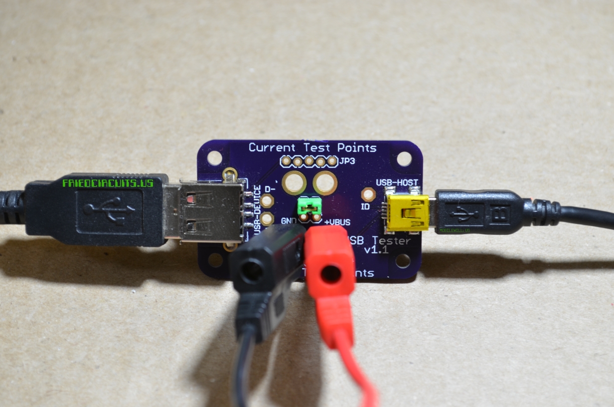
- Current Test points
- Provides banana size holes for Digital Multi-Meter (DMM) test leads.
- The right one is connected to USB Mini and the left one is USB A.
- Current would past from right to DMM to left one.
- Current Jumper
- Remove before testing current with DMM.
- When jumper is installed allows to bypass current testing
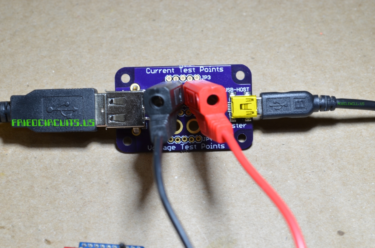
- Voltage Test Points
- Banana size holes for DMM or 0.1″ header for test leads
- Right is VCC.
- Left is GND.
- Breakout of all connections, used for male headers to backpack
JP3 and JP4 are connections for backpacks and are labeled on the rear of the PCB.
USB A port on the left connects to your device. USB B mini connects to your computer or power source.
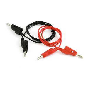
You can use leads like these from SparkFun to connect your DMM to the USB Tester: http://www.sparkfun.com/products/507
Note: Be careful when using test leads as you can easily short out the power connections. Your computer’s USB port should protect itself but don’t rely on it.
How to:
This is a general guide on how to use the USB Tester to monitor current and voltage using a Digital Multi-Meter. Your meter may operate differently in which case you should refer to the operation manual.
Measuring Current:
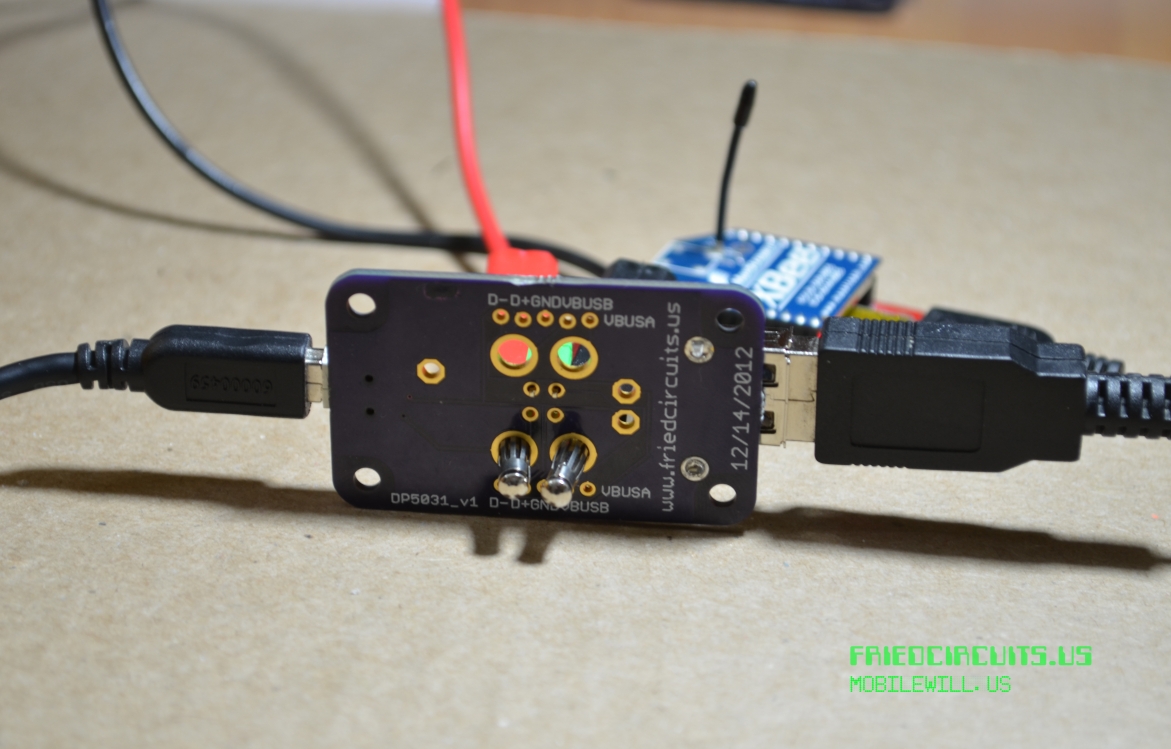
USB Tester Current Setup

Connections to DMM for Current
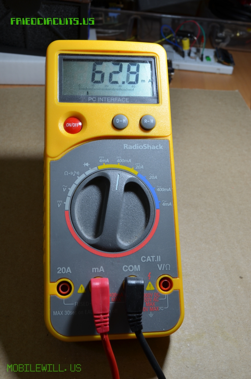
DMM Measuring current of an Xbee Series 1
Your DMM might be auto ranging, if not make sure you select the proper setting for the current you are measuring. Otherwise you can blow a fuse. This DMM has two fuses one for the 4mA/400mA range and another for the 20A range. For 20A there is a separate port. Since USB is 500mA but other devices while charging can be more you should use the higher setting.
Measuring Voltage:

USB Tester setup for voltage
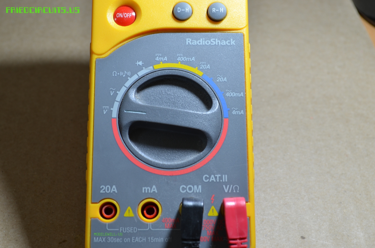
DMM setup for voltage measuring
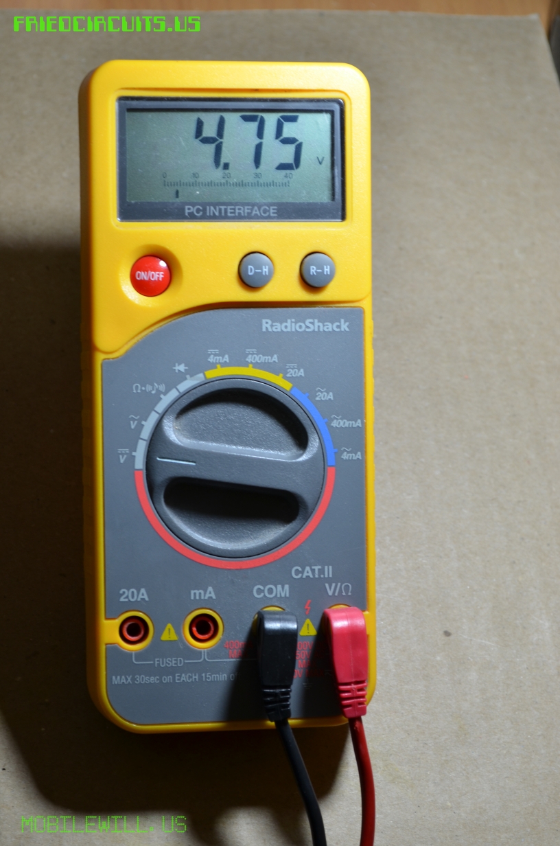
DMM measuring voltage to an XBee
Things to look out for:
Be careful that the leads on the rear don’t touch. One way to prevent this is to insert one lead from the opposite side instead of both on the same side of the PCB. If you have the headers and/or jumper soldered on, it will keep the leads from going too far in so they cannot touch on the back side.
USB Tester, rear side while measuring voltage
Versions:
1.0: Initial
1.1: Ground plane both sides
1.2: Different USB A footprint for better alignment during assembly
1.3: Updated traces for D-\D+ for good measure, and increased thickness of VCC
Comments 4
Hello, We have purchased one of these units, and plan to purchase 2 more. However, we would like to automate the data logging. Instead of using Wizkers in a manual mode, we are writing a Python script to manage a full test station. Can you tell us what format the data is transferred in? We just want to log the data in a simple csv format with the python script reading the COM port. Thanks for your help.
William Milam
hi William
Did you manage to find out the format of the data?
lafe William Milam Yes, it took a little time, but I found that it created data using the JSON format. Python has a library for JSON formatting, so that part was easy. It is working well for us.
William Milam lafe thanks a lot!!