
Info: USB Tester OLED Backpack
Purchase: Tindie
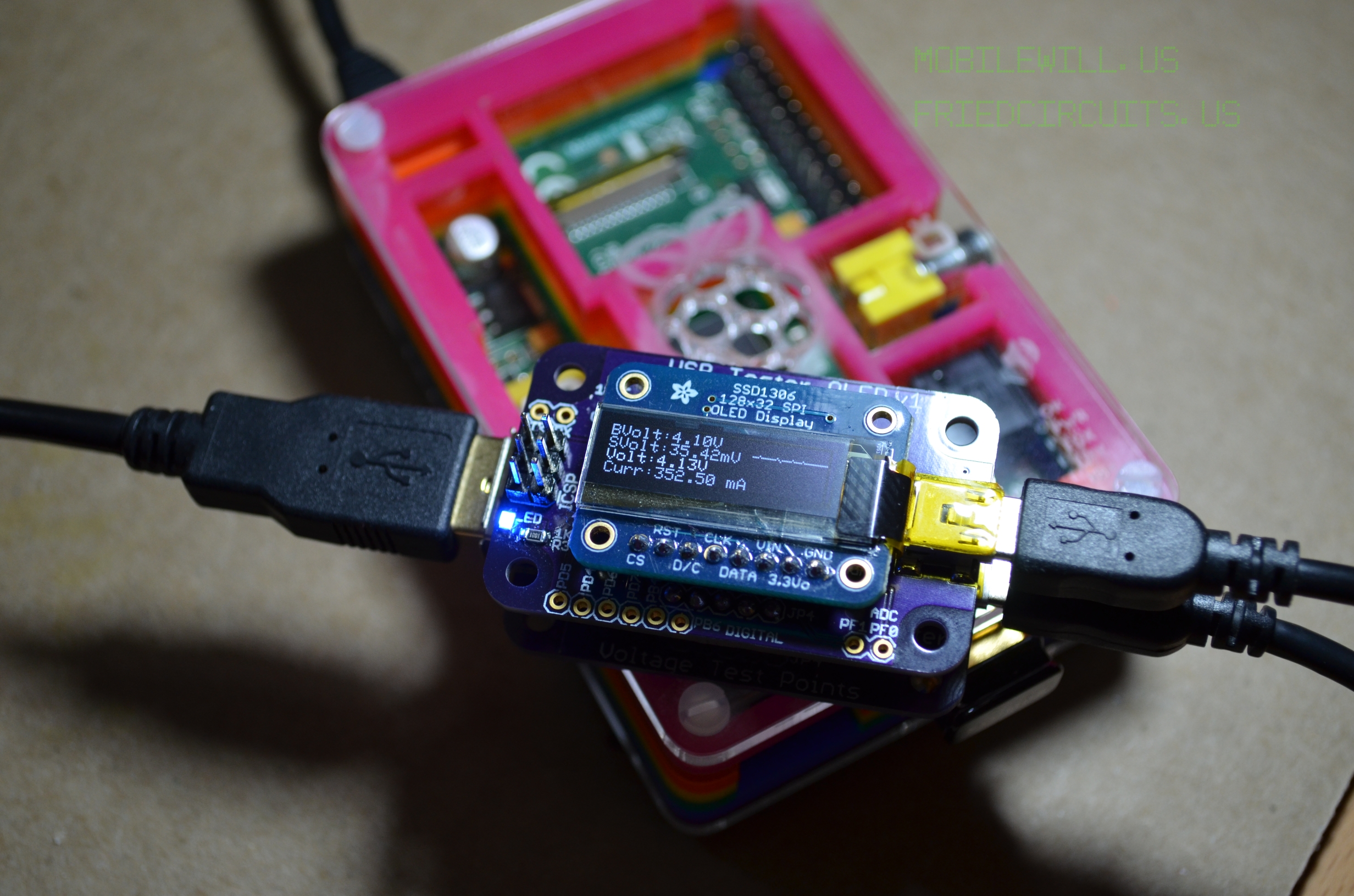
The USB Tester OLED backpack is an add-on for the USB Tester for displaying and data logging the voltage and current for any USB device. This allows you to easily monitor USB devices without having to connect a Digital Multi-Meter. This guide covers how to assemble the few parts that it comes in.
The OLED Backpack comes with the following parts:
- 1x Microcontroller Adapter Board
- 1x Adafruit SPI OLED Display
- 1x 8pin Male Header
- 2x 5pin Female Headers
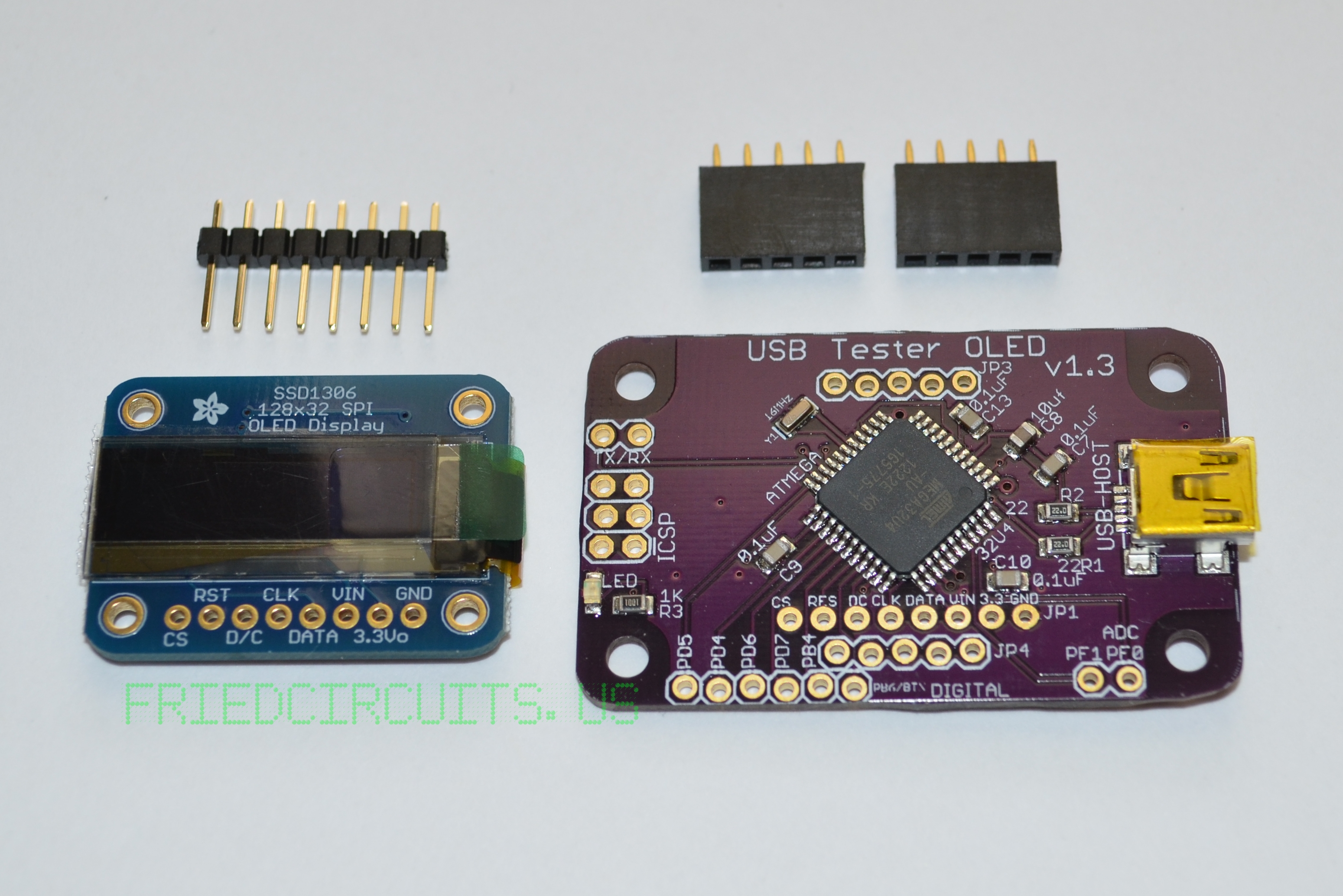
Parts included with OLED Backpack
The headers come loose so that you can use the backpack however you want, for example to measure other current sources without the USB Tester Base.
1. Female Headers
First you want to solder the two female headers that are included. They attach to the pin holes labeled JP3 and JP4. There are two ways you can solder them to keep them aligned.
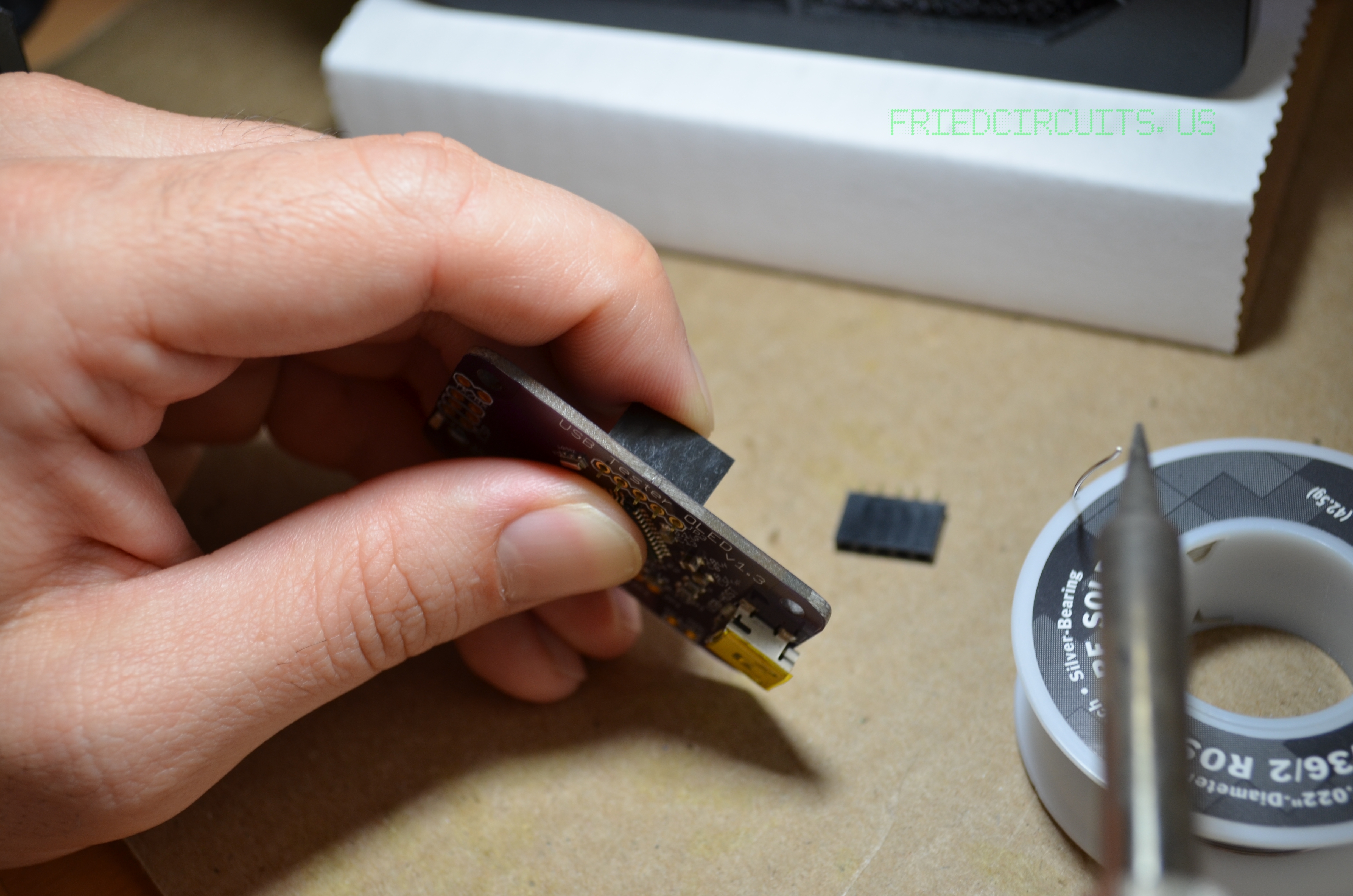
Soldering headers using your finger to hold it in alignment.
Either by holding it straight with one finger (as shown above) or by using the USB Tester (shown below).

Place female headers on USB Tester
Solder one side of header
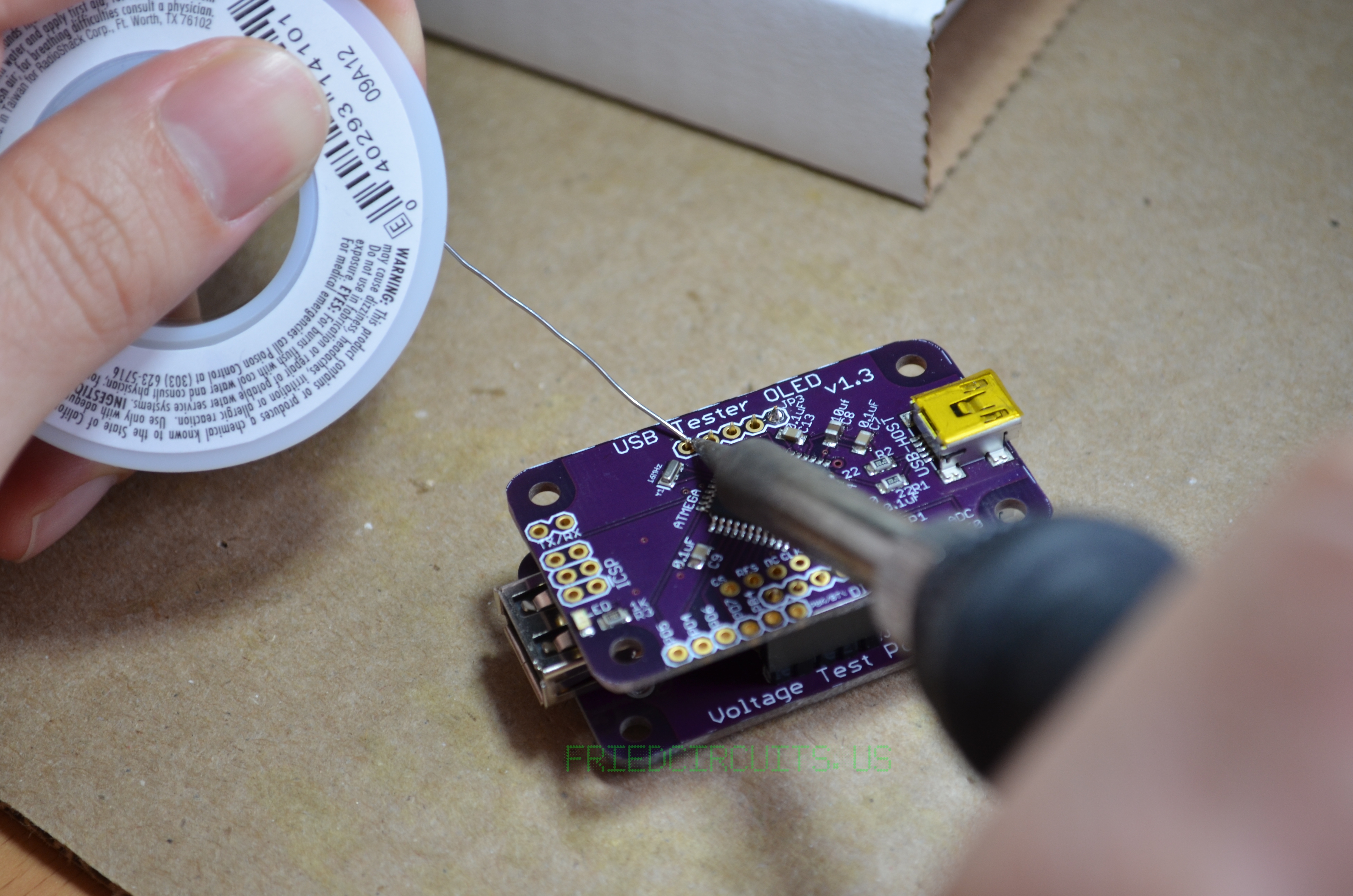
Solder other side of header after checking alignment

Solder rest of header pins
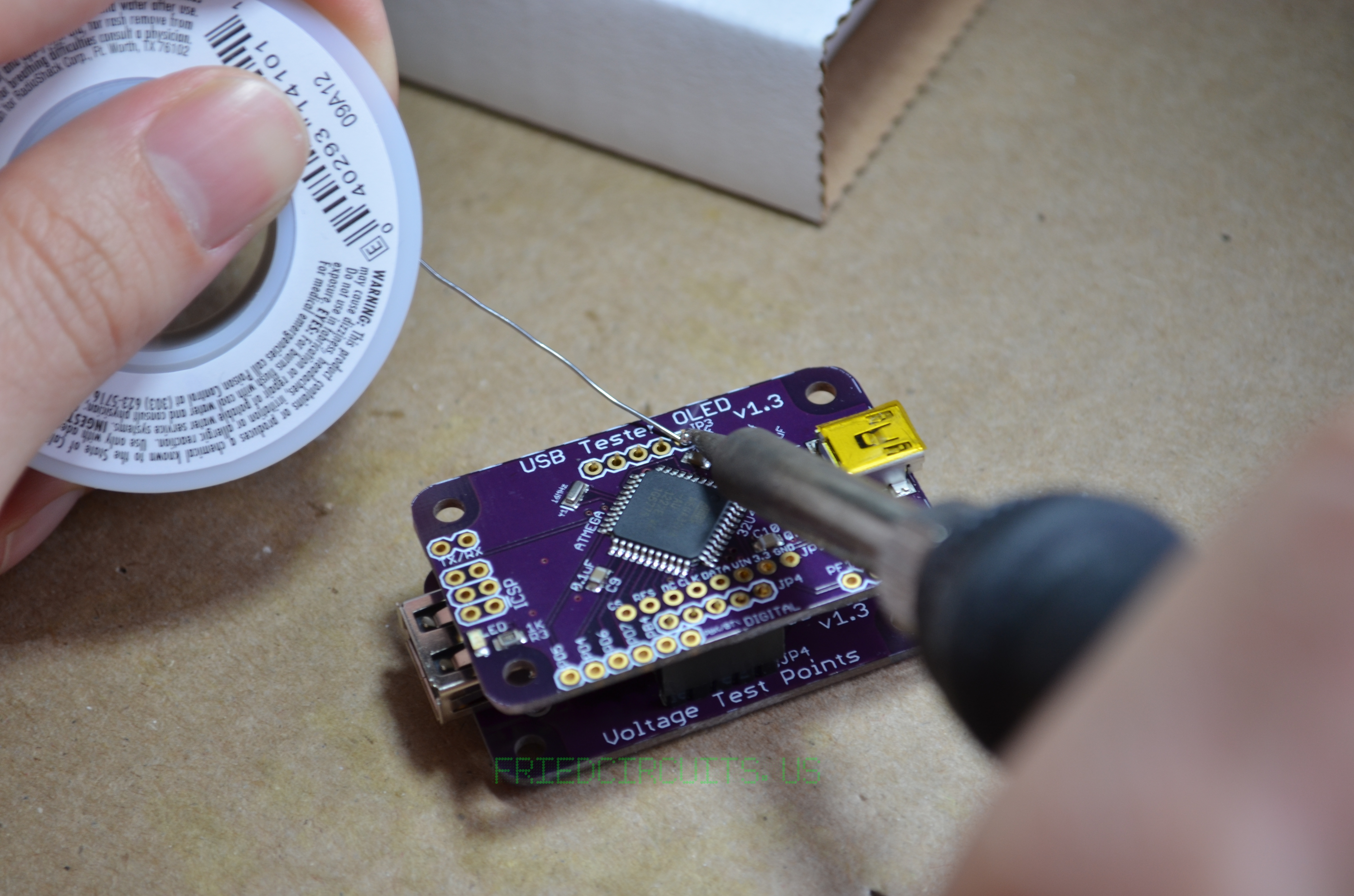
2. OLED Display
Start by holding the header in place with your finger in the middle so you can solder one side. Then check the alignment and adjust as needed. Solder the other side, check alignment and then the rest of the headers.
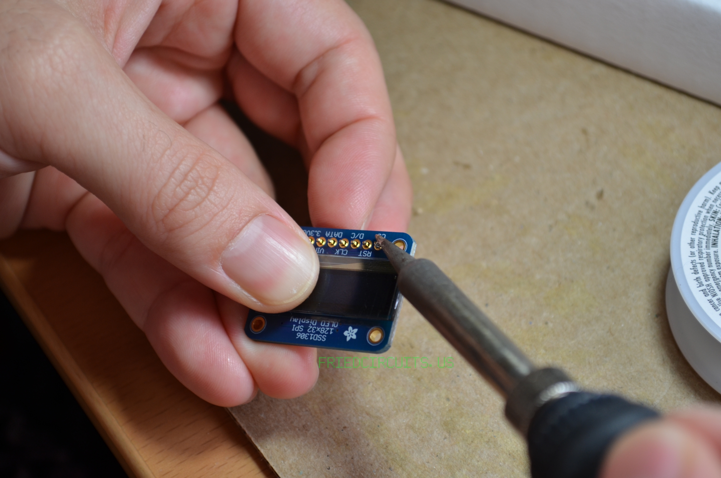
Solder one side of header and check alignment
Solder rest of header pins
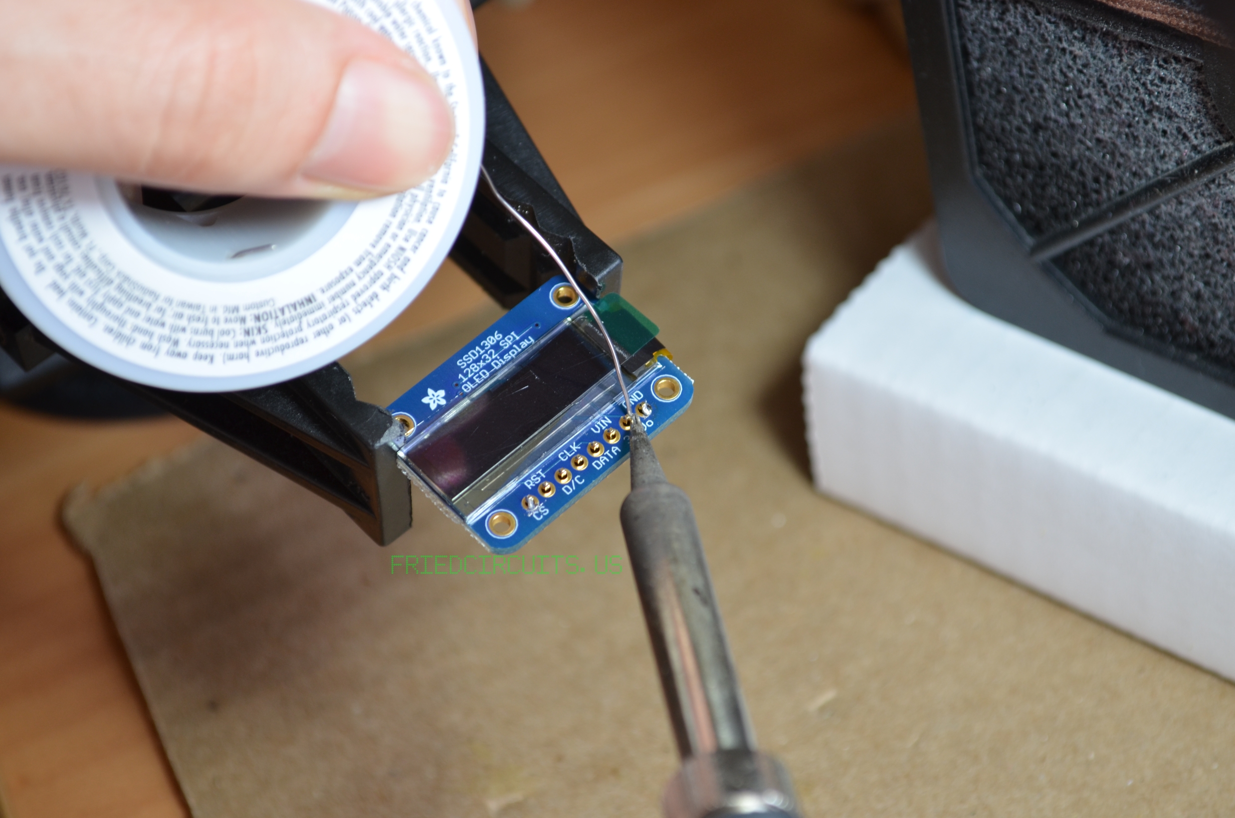
Finally you want to solder the OLED display to JP1. Once you solder you can adjust the height of the display to your liking. If you mount it at its lowest height, make sure the back side components don’t touch the components on the OLED Adapter PCB. After verifying this step, finish soldering the header.
Hold display and solder on side
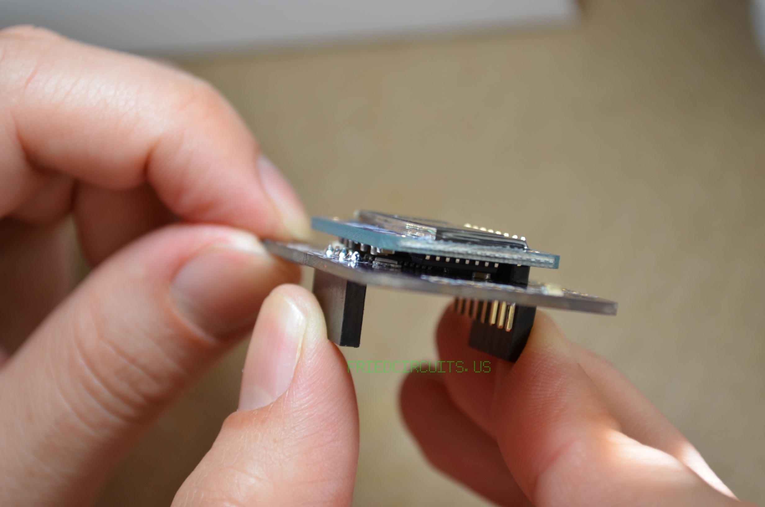
Check gap between display and PCB before soldering all pins

Finish soldering header
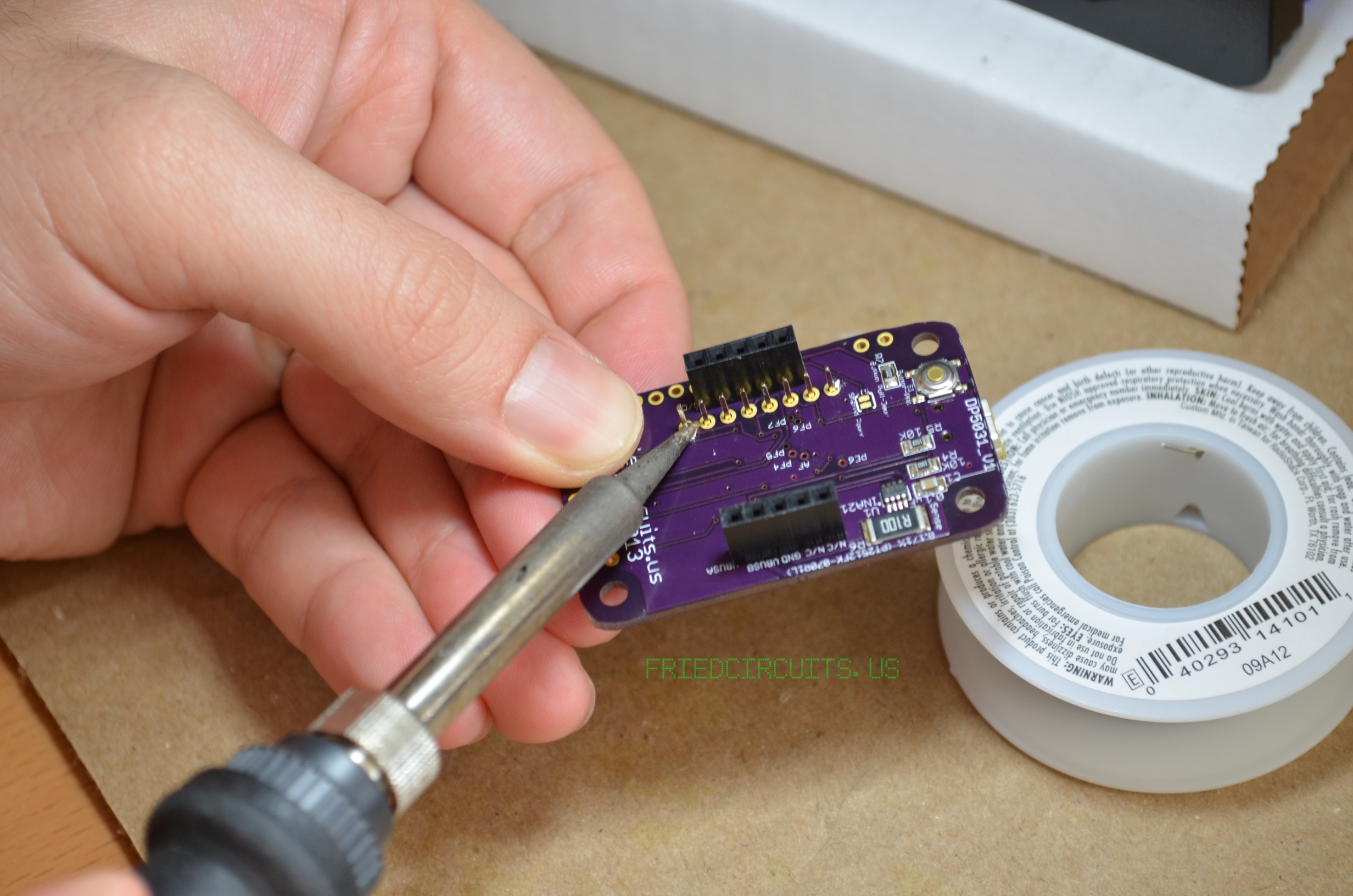
3. Attach to USB Tester (Optional)
If you own the USB Tester you can now attach the OLED Backpack to the top of the USB Tester. If you haven’t soldered the male headers that came with it you can do that now. You can find the guide here.
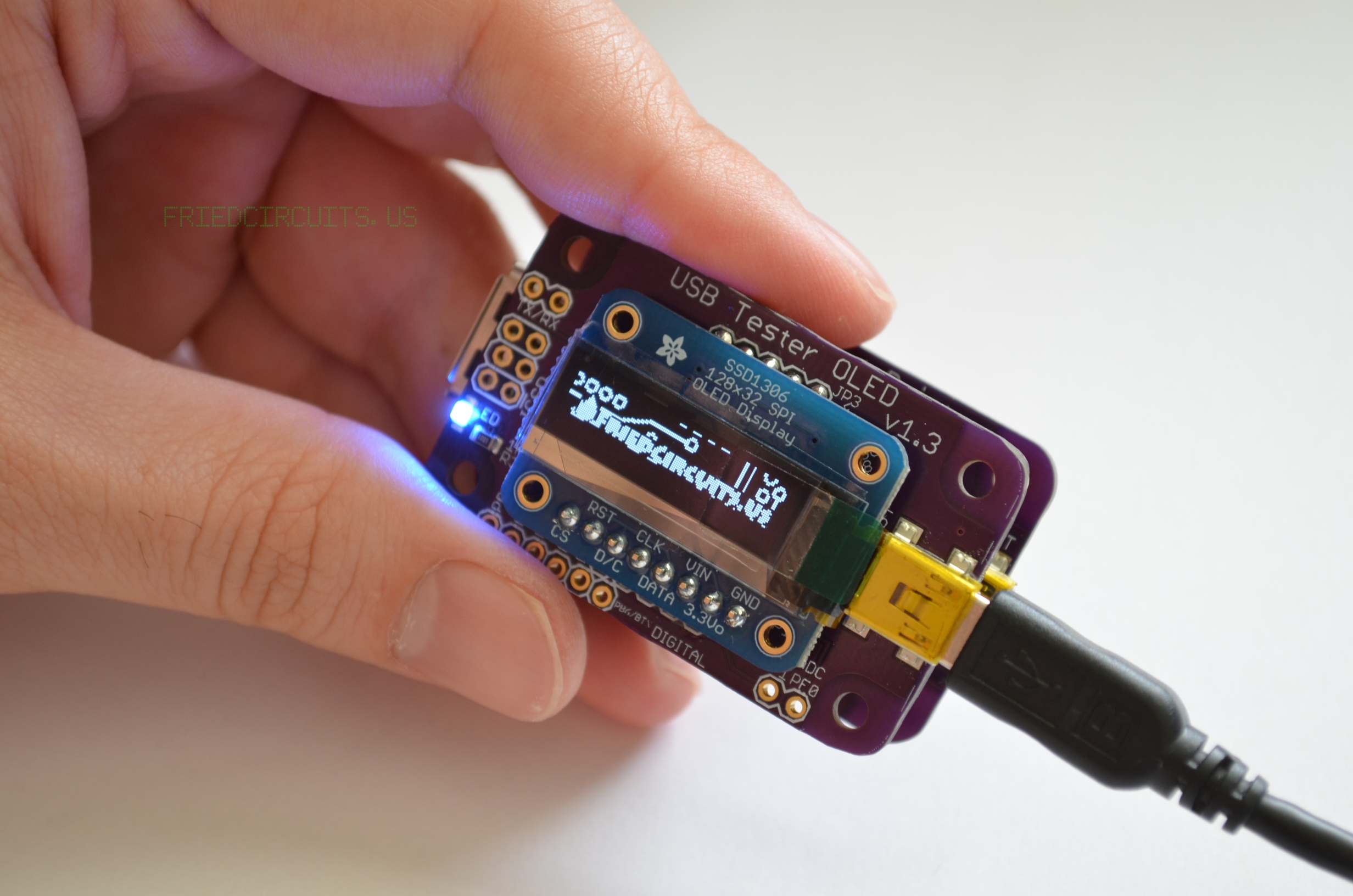
Powering up OLED with USB Tester
For a detailed description of the parts and connections of the OLED Backpack click here.