
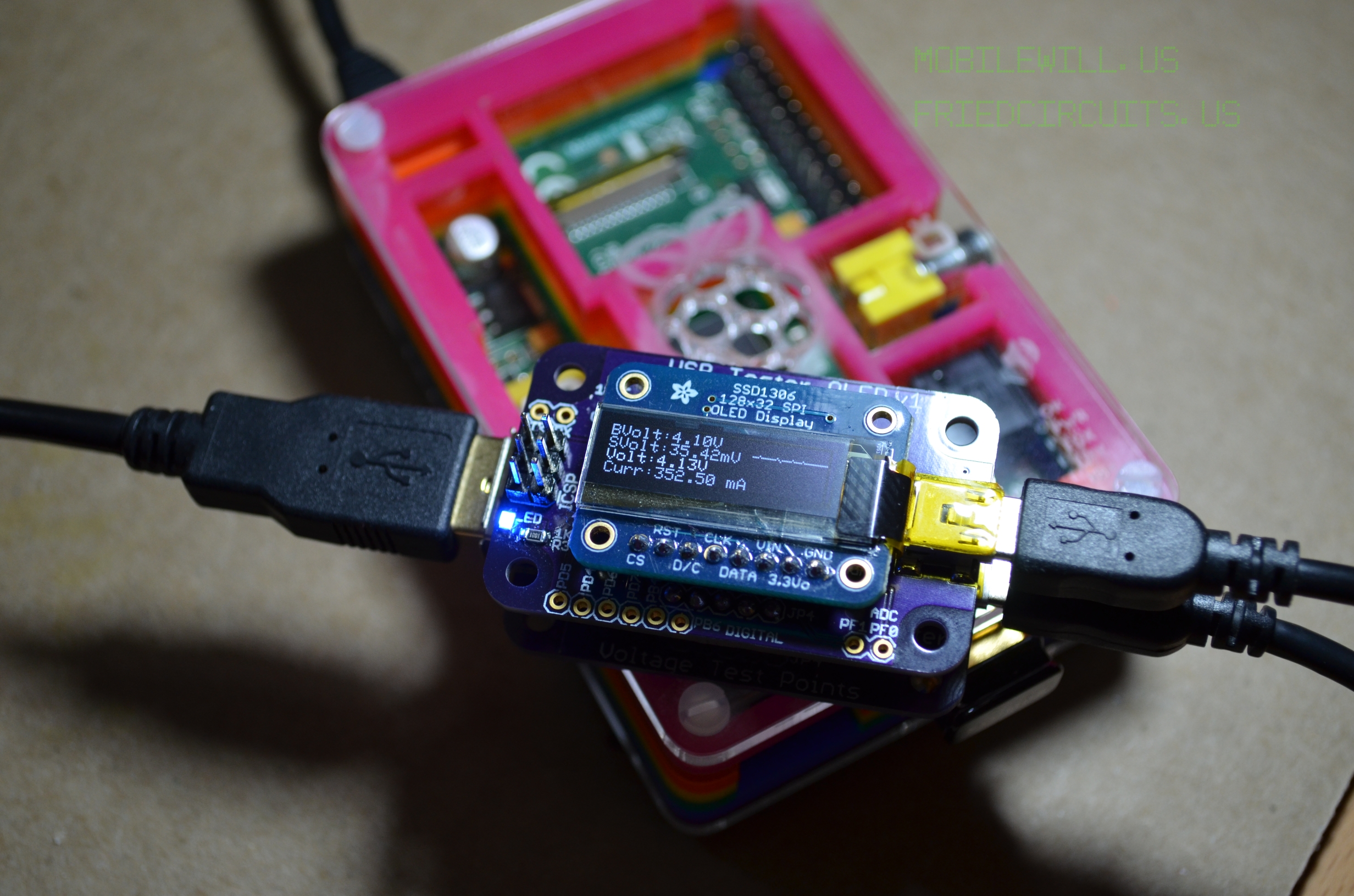
Introducing the new USB Tester OLED Backpack! This is an add-on for the USB Tester which can be found here: https://tindie.com/shops/FriedCircuits/usb-tester/. Instead of having to connect your Digital Multi-Meter to the USB Tester you can attach this backpack and get the readout directly on the display. The backpack consists of two PCBs: the first PCB has the microcontroller with sensing circuits and the second contains the OLED display and driver. The OLED display is made by Adafruit Industries and mates directly to the USB Tester OLED Backpack. The left side of OLED display will show the instantaneous bus voltage, shunt voltage drop, device voltage, and current usage. The right side will display a short term graph of the last minute or so of current usage.

USB Tester with OLED Backpack measuring a Raspberry Pi
Features:
OLED Backpack:
• Atmega 32u4 (All unused pins are broken out)
• INA219B Current IC from TI
• INA219B can measure up to 3.6Amps in its current configuration. (Adjustable in library code)
• LED Threshold Warning indicator (configurable via desktop application)
• Can be powered from the same source as the measuring device or from a separate USB port
o Doesn’t affect measurements
• Header connection to OLED display
• Arduino Leonardo bootloader for easy hacking
• Source code will be available for download
Adafruit OLED Display:
• 128×32 pixel monochrome OLED Display
• SPI Interface to Microcontroller
• Daylight readable
• Low power with OLED technology
• Able to display graphics and characters
Includes:
• 1x Backpack addon with microcontroller
• 1x SPI OLED Display from Adafruit Industries (includes males headers)
• 2x Female headers for backpack
One of the important features added during development of revision 2 was an LED to indicate the proximity to the mA set point. The closer the current draw gets to the set point, the faster the blink rate of the LED. Once the current draw reaches the set point, the LED will stop blinking and stay lit. You can change the behavior by modifying the source code available at the source link to the right.
The OLED backpack can also be connected to a desktop running Windows\OSX\Linux. This connection will let you set the set point, view and record the current, voltage, and wattage via a free Java application download. The source code is included with the Java application so you may modify it to meet your needs.
All of the pins that aren’t being used have been broken out for use in your own projects. One example might be to use the extra pins as triggers. You could set a pin high if the current reaches a certain limit.
The original design called for a switch to select between external / PC power and shared power for the USB Tester backpack. This turned out to be unnecessary since it doesn’t affect the current measurement the way the power is routed. If both are powered from the same source there will be a reduction of about 40mA in maximum power you can draw for the device you are measuring.
Instead it will have a solder jumper if you ever needed to separate the power sources. I am working on the feasibility of a multipurpose button on the underside. One use could be used for controlling local data logging. Let me know if you would like to see these or any features in the production version.
*Note: The current sensor is not limited to 500mA so you could use the backpack to measure other higher current draw devices such as a phone charging or Raspberry Pi Model B. The sensor can measure up to 3.6Amps or less with higher resolution. This is all based on configuration setup in the library. You can view the datasheet for the current IC here: http://www.ti.com/lit/ds/symlink/ina219.pdf
You can find more photos here: http://www.mobilewill.us/2013/01/usb-tester-oled-backpack-v1-prototype.html
Documentation: Here
Source Code: Here
If you would like to purchase one you can find it on Tindie: https://www.tindie.com/shops/FriedCircuits/usb-tester-oled-backpack-with-display/
Comments 12
Anyone have a 3d model of an enclosure for this tester? It would be great to just print one… just don’t have the time to design one from scratch…
skaterdad I haven’t made anything but this case fits since I use the Dangours Prototypes Sick of Beige standard PCB size. http://www.mobilewill.us/2013/03/usb-tester-and-sick-of-beige.html. I am working on getting a bunch of them. Makes it easier for people in the US.
MobileWill skaterdad I think I’d rather see it as a 3d printed enclosure with nice opening for LCD on one side and correct holes for banana plugs in the back (so they don’t short). If someone designs one that is descent and I can print, I’ll happily print a few more and send to the designer.
I just recieved the entire kit (including acylic base) found & installed the arduino-1.0.5-windows.exe, now I cannot get my Atmel based maXTouch controller to be recognized through your device – it cannot connect. Any idea’s? Also the Tx/Rx – could I potentially (that is if I can get communication going through the USB OLED Tester) send/recieve via RS232?
john mems engineer Hi, does any other device work? Which USB port are you using, the backpack or the base?
The Tx/Rx is just to talk directly to the microcontroller but would need firmware supper.
MobileWill john mems engineer – actually I just figured it out – I have to plug into the bottom board & leave the top board unplugged. I guess I got confused what is backpack & what is base, it is all goo now. is there a user document that explains the pins, & the button function (I notice I can change the display) very cool. Have a feeling I will need to order more of these when they are available.
john mems engineer I have this page http://learn.friedcircuits.us/usb-tester-oled-backpack/ but looks like I need to fix the links between the different OLED Backpack posts. They are not linked to the right pages.
I hope to have more ready in a few weeks with some new surprises….
MobileWill john mems engineer how can I tell if the unit I have has the latest firmware/libraries? I am brand new to Arduino.
john mems engineer If you have the multiple screens and holding the button shows reset you are updated.
john mems engineer I need to double check the working package zip is up to date, I am pretty sure it is.
MobileWill john mems engineer Yep – I got multiple screens, Reset works. Thanks
I just received and assembled the USB Tester and backpack. Great product. I’m noticing that for some reason, on the top portion of the OLED display, it appears that every other line of pixels is not displaying. I have not tried to do any firmware updates, etc yet. For the display modes with the larger numbers, one can read it (still with the missing rows of pixels) but with the smaller text, it is unreadable. Could this be a firmware issue of some sort, or do you think I just have a bad display?